


26 Assembly
WPMAN0142 (Rev. 9/1/2004)
ASSEMBLY
Always wear relatively tight and belted clothing
to avoid getting caught in moving parts. Wear
sturdy, rough-soled work shoes and protective
equipment for eyes, hair, hands, hearing, and head;
and respirator or filter mask where appropriate.
Before working underneath, raise mower to
highest position and block securely. Blocking up
prevents mower dropping due to hydraulic leak
down, hydraulic system failures, or mechanical
component failures.
DEALER SET-UP INSTRUCTIONS
Assembly of the mower is the responsibility of the
Frontier dealer. It should be delivered to the owner
completely assembled, lubricated, and adjusted for
normal conditions.
Complete the checklists on page 30 when assembly is
complete.
IMPORTANT
Gearbox was not filled at factory. It must be ser-
viced before operating mower. Failure to service
will result in damage to the gearbox. See page 29.
The mower is shipped partially assembled. Assembly
will be easier if the components are aligned and loosely
assembled before tightening hardware. Recommended
torque values for hardware are located on page 41.
Select a suitable working area. Open parts boxes and
lay out parts and hardware to make location easy.
Refer to illustrations, accompanying text, parts lists and
exploded view drawings.
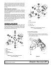
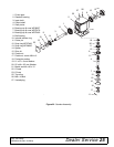
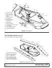
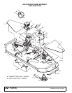
Rear Driveline Installation (Figure 23)
Attach counter-cone shield (6) over gearbox output
shield (7) using four 5/16" cap screws (3) or M8 cap
screws (4) and washers (5).
Attach implement end of driveline (1) to gearbox output
shield (7).
Fasten tether chain to bracket (8) as shown, securing
with left front gearbox mounting bolt. Chain must be
loose enough to allow full joint articulation.
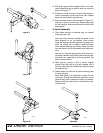
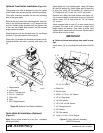
Hitch Installation (Figure 24)
The GM1190R is shipped with the Category 1 hitch
pins in the shipping location. Remove bolt (1) and hitch
pin bracket (4). Remove the hitch pin from the shipping
location and place it in the end hole. Insert the hitch pin
bracket (4) into the mast plate as shown. Slide sleeve
(3) through holes flush with outside of mast plate and
and A-frame (5). Secure with bolt (1), washers (2), and
hex locknut (7). Repeat for other side.
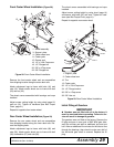
Remove bolt (8) and assemble 3-point brace bars (9)
on outside of A-frame bars (5). Re-install bolt (8)
through bars, spacer (10), and top-link clevis (11).
Secure with flange lock nut (12).
Tighten all hitch assembly hardware according to spec-
ifications in Bolt Torque Chart.
Install PTO hanger bracket (14) to upper mast assem-
bly. Secure with flange locknut (12). Do not over-
tighten locknut. PTO hanger bracket should be able to
rotate freely out of the way when the mower is in oper-
ation.
Figure 23. Rear Driveline Installation
CAUTION
W
W
ARNING
ARNING
7
6
2
1
3, 4, 5
8
Tether Chain
CD5949
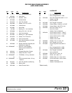
1. Driveline
2. Shield Retainer
3. Screw, HHCS 5/16" x 3/4
4. Screw, HHCS M8 x 1.25 x 20
5. Washer, 5/16" Standard
6. Counter-cone Shield
7. Gearbox Output Shield
8. Tether Chain Bracket