


766238 6/07 6-3
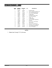
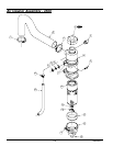
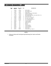
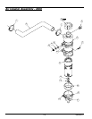
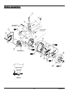
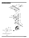
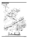
Brake Assembly
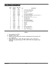
NOTES:
1. Torque to 75-80 Ft. Lbs.
2. Torque to 425-450 Ft. Lbs.
3. Pull plastic strap only tight enough so cable is parallel to backing plate. Cut
off excess strap.
4. Use plastic strap to hold right brake cable to tractor frame after cable is
attached to brake activation assembly. Pull strap tight, cut off excess strap.
5. Apply 3 drops of 609 Loctite to taper on wheel motor axle as shown.
Assemble within 15 minutes. Do not put drops on threads or backside of
nut.
6. Install brake shoe with longest pad toward front of tractor (both sides).
7. Install strut with longest notch toward front of tractor (both sides).
8. Used on tractors with serial number prior to 04014000.
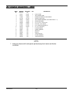
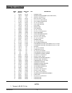
INDEX
NO.
SERVICE
PART NO.
MFG. PART
NO.
QTY. DESCRIPTION
1 383687 383687 1 LEVER AND CABLE ASSEMBLY
2 072405 N/A 1 BRAKE HANDLE LEVER ASSEMBLY
3 072389 N/A 1 RIGHT BRAKE CABLE ASSEMBLY
4 032052 N/A 1 LEFT BRAKE CABLE ASSEMBLY
5 060889 060889 3 PLASTIC STRAP
6 061812 061812 8 CS .50-13 X 3.50 HX G5 ZN
7 333104 333104 1 LH WHEEL MOTOR SPACER
333112 333112 1 RH WHEEL MOTOR SPACER
8 792341 792341 2 WHEEL MOTOR
007914 N/A 2 WHEEL MOTOR
9 792457 N/A 2 WOODRUFF KEY
064337 N/A 2 WOODRUFF KEY
10 072694 072694 4 STEM
11 072728 072728 2 DUST COVER
12 356360 356360 1 L/H BACKING PLATE
356352 356352 1 R/H BACKING PLATE
13 017046 017046 8 LW .50 MEDIUM SPRING ZN
14 067918 067918 8 NT .50-13 HX G8 ZN
15 072769 072769 2 LEVER PIN LOCK
16 072710 072710 1 BRAKE SHOES (SET OF 4)
17 072678 072678 4 HOLD DOWN SPRING
18 072686 072686 4 LOCK CUP
19 037788 037788 2 SPRING
20 072702 072702 2 ADJUSTER
21 034652 034652 2 SPRING
22 072751 N/A 1 L/H LEVER AND PIN ASSEMBLY
N/A 241018 1 LEVER ASSEMBLY PIN
N/A 241034 1 L/H LEVER
072744 N/A 1 R/H LEVER AND PIN ASSEMBLY
N/A 241018 1 LEVER ASSEMBLY PIN
N/A 241000 1 R/H LEVER
23 072736 072736 2 STRUT
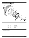
24 423830 423830 2 HUB AND DRUM ASSEMBLY
25 024281 N/A 10 MOUNTING BOLT
26 706192 N/A 2 NUT
8
8