


7662383 6/07 15-3
4500 Engine & Hydraulic Set-Up Procedures-Mechanical Gov
4500 ENGINE & HYDRAULIC SET-UP PROCESS IN TEST & ADJUST POSITION
Step 1. Check fluid levels.
• Engine Oil Capacity: 3 & 1/2 Quarts
• Hydraulic System Capacity: 3 & 1/2 Gallons (With 11 ounces of Lubrizol #5178 additive.)
• Cooling System Capacity: 3 & 1/4 Gallons of 50-50 Mixture Ethylene Glycol & Water
Step 2. Adjusting the Neutral Lock Switch
• The neutral lock switch (023002) can be damaged if not properly adjusted. To insure proper adjustment,
put the front neutral lock (467811) in the down position. Check the switch to make sure both switch boot
nuts (023044) and switch boot (023051) are installed. With the switch loosely installed in position, begin
to move it upward until you hear the switch click. Lock the switch boot in position with switch boot nuts.
Continue to hold switch in this position and tighten the switch mount bolts and nuts. Warning: the switch
can be damaged by overtightening. After tightening the switch mount fasteners, check the installation by
opening and closing the front neutral lock lever several times to make sure the switch is clicking and that
it is not being forced down past its travel length.
Step 3. Choke Adjustment (done while engine is not running)
• Position choke lever in middle of slot (front of tractor on panel located next to footrest). Using the choke
lever on the carburetor, position the choke plate in a vertical position. With the choke lever and the choke
plate in this position, attach the choke cable to each. Cable will be correct length.
Step 4. Engine Speed Setting
• Engine speed is pre-set at factory.
• Check throttle control to make sure it is in the correct positions with respect to the engine speed specifica-
tions.
+ Idle = 950-1050 RPM’s
+ Maximum = 3250 RPM’s
• Check speed with pump disengaged.
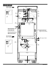
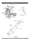
Step 5. Set and Adjust Governor Speed Control Linkage
a. Remove oil level plug on R/H lower front of governor. If no oil is
present, remove oil fill plug on top of governor and add 10W40 motor
oil until it leaks out at oil level hole.
b. With engine at operating temperature, adjust carburetor idle mixture
screw by turning clockwise until RPM’s drop from being too lean.
Turn idle mixture screw counter-clockwise until RPM’s increase and
then drop from being too rich. Turn idle mixture screw clockwise until
RPM’s increase and engine runs smooth with no pulsations.
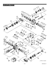
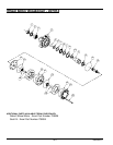
c. (See View A) Adjust eye-bolt (B) to 1.03 inch dimension. Set surge
screw (C) to .70 inch dimension. Set high speed stop screw (E) to
.65 inch dimension.
d. Put slight tension on governor spring with lever (A) and install throttle
rod hardware between governor throttle lever and carburetor lever.
Adjust length of linkage rod so that carburetor lever is about 1/32 to
1/16 inch off it’s wide open stop. Tighten locking nuts on linkage rod.