7662383 6/07 15-5
4600 Engine & Hydraulic Set-Up Procedures
4600 ENGINE & HYDRAULIC SET-UP PROCESS IN TEST & ADJUST POSITION
Step 1. Check fluid levels.
• Engine Oil Capacity: 5 Quarts
• Hydraulic System Capacity: 3 & 1/2 Gallons
• Cooling System Capacity: 2 & 3/4 Gallons of 50-50 mixture ethylene glycol & water
Step 2. Adjusting the neutral lock switch
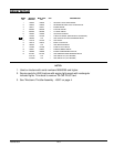
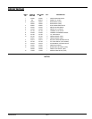
• The neutral lock switch (023002) can be damaged if not properly adjusted. To insure proper adjustment,
put the front neutral lock (467811) in the down position. Check the switch to make sure both switch boot
nuts (023044) and switch boot (023051) are installed. With the switch loosely installed in position, begin
to move it upward until you hear the switch click. Lock the switch boot in position with switch boot nuts.
Continue to hold switch in this position and tighten the switch mount bolts and nuts. Warning: the switch
can be damaged by overtightening. After tightening the switch mount fasteners, check the installation by
opening and closing the front neutral lock lever several times to make sure the switch is clicking and that
it is not being forced down past its travel length.
Step 3. Engine speed setting
• Engine speed is pre-set at factory.
• Check throttle control to make sure it is in the correct positions with respect to the engine speed specifica-
tions.
+ Idle = 900-1000 RPM’s
+ Maximum = 3100-3200 RPM’s
• Check speed with pump disengaged.
Step 4. Check the rear neutral lock (483735) to be sure it is free to fall into the down (locked)
position.
Step 5. Fill and Flush the Hydraulic System
Step 6. Steering Lever Adjustment
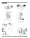
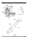
• Check and set measurement for the neutral positioning linkage. Do not tighten the two front nuts on the
threaded rod (766303).
• After flushing the hydraulic system, the hydraulic oil will be sufficiently warm to make the final steering
lever adjustment.
• Lock the steering lever into position using front neutral lock (467811) and rear neutral lock (483735).
• If the wheels rotate, loosen the jam nuts on the turnbuckles. Adjust the turnbuckles until the drive wheels
do not rotate either clockwise or counter-clockwise. Retighten the turnbuckle jam nuts.
• Tighten the two front nuts on the threaded rod (766303) making sure the rod does not shift position.
Warning: make sure all locking nuts and fasteners are tight on turnbuckles.


