41
BAGGER ASSEMBLY
Assembly directions, catcher bag
(Part No. 539106667)
WARNING!
DO NOT use or start the engine until the
catcher bag is in place.
WARNING!
Machines equipped with a catcher MUST
not be used with defective catcher bags or
without the catcher bag.
They pose a risk of thrown stones, eye in-
jury and inhalation of pollution.
1. Remove rear cover, it is not used with the
bagger attachment.
2. Disconnect cable on handle, remove clutch bail
from handle.
3. Remove handle from unit saving hardware.
4. Place a stable support under the rear frame to
support the unit when the rear wheels are re-
moved.
5. Remove the two (2) retaining rings on the rear
wheel (they are not reusable, new rings are
provided in the kit). Remove wheel from rear
axle. (Some units have cotter pins instead of
retaining rings.)
6. Loosen one (1) set screw on the locking col-
lar. Using a punch loosen the locking collar
on the rear axle. Repeat on the other side of
unit.
NOTE:Rubber flapper does not have to be removed.
8. Remove bearings from the frame, retain hard-
ware.
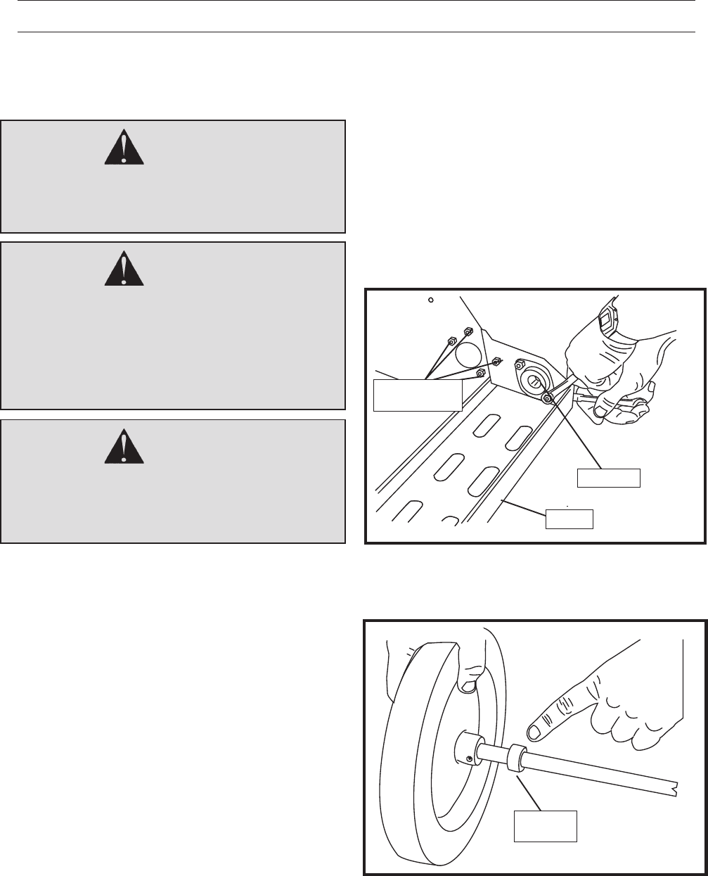
9. Install tray matching screw holes in main frame.
See Figure 1.
FIGURE 1
10. Apply bearings on the inside of the tray, DO
NOT tighten hardware, just snug it. See Figure 1.
BEARING
11. Add locking collar to shaft, install shaft through
bearings and tray. Place the other locking col-
lar on the shaft. See Figure 2. Using a punch
tighten the locking collars, then tighten the set
screw. Repeat for the other side.
FIGURE 2
LOCKING
COLLAR
ATTACH TRAY
TO FRAME
DT09
DT10
TRAY
7. Remove rear axle from unit. The wheel that is
pinned to the axle can remain on the axle.
NOTE: If axle is rusty, remove rust with fine sandpa-
per.
WARNING!
DO NOT attempt to unblock bagger chute
while engine is running. Stop engine be-
fore removing grass and debris.


