


English - 43
Assembly
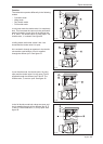
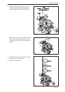
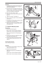
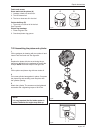
1. Thread the throttle cables in the connection M
as outlined in gure 55. NOTE! The gure is
shown from underneath.
2. Run the fuel hose D through hole K and hoses
B and C in hole L. See gure 55. Pull the hoses
so that the collars are on each side of the bot-
tom on the carburettor compartment.
3. Tighten the chain catcher in place.
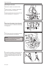
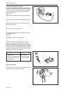
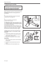
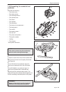
4. Press the movement limiter H into position. See
gure 53.
5. Tighten the screws F. See gure 51.
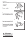
6. Hook on the throttle cable E in the intake bellow.
See gure 50.
7. Fit the tank unit. The two short screws are tted
to the bottom of the handle bar.
8. Assemble the carburettor as outlined in “Assem-
bling the carburettor”. Assemble the air lter
and cylinder cover.
Repair Instructions
7.17 Vibration damping system
Dismantling
1. Dismantle the following parts:
• Bar and chain. See the Operator’s Manual.
• Cylinder cover. See the Operator’s Manual.
• Tank unit and handle. See “Dismantling the
tank unit”.
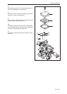
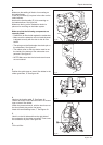
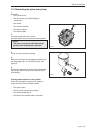
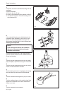
2. Dismantle the spring on the handle bar using a
4 mm Allen key (see gure 57).
3. Dismantle the springs on the tank unit using
a 4 mm Allen key (tool 502 50 18-01). See
gure 57.
Cleaning and inspection
Clean and inspect all parts.
Assembly
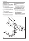
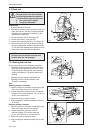
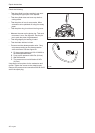
1. Fit the springs on the handle bar using a 4 mm
Allen key (tool 502 50 18-01).
2. Assemble the following parts:
• Tank unit and handle. See “Assembling the
tank unit”.
• Cylinder cover. See the Operator’s Manual.
• Bar and chain. See the Operator’s Manual.
Fig 55
Fig 54
Fig 56
Fig 57