


English - 21
Safety equipment
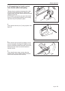
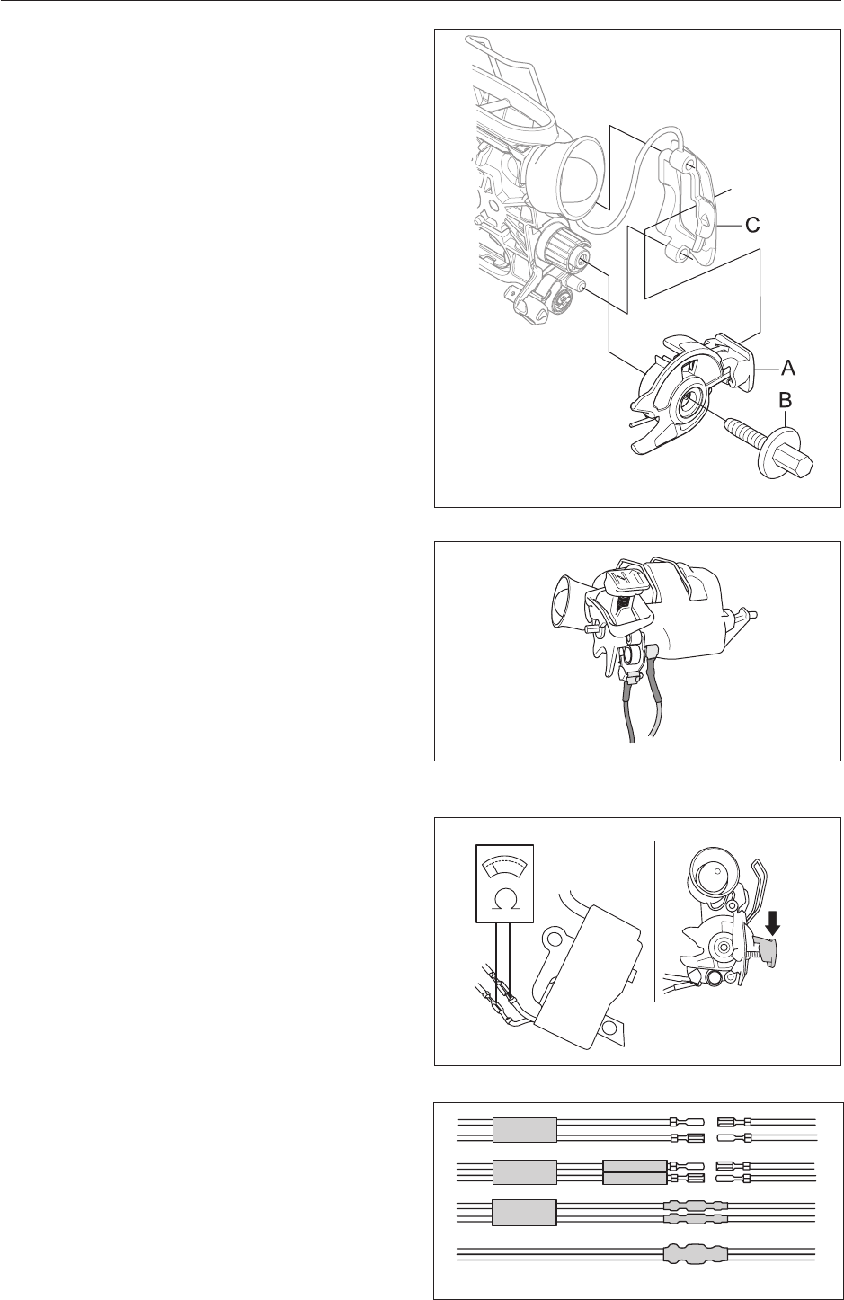
6.8 Resistance test - stop function
Dismantle the ignition module as outlined in
“7.7 Dismantling the ignition module and ywheel”.
Cut open the shrink tube covering both cables and
shrink tubing that encloses the cable ends.
Clean the contact areas and check resistance in
the following way:
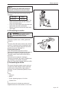
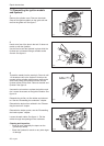
Test the resistance by connecting a multimeter to
the cable ends. NOTE! The power switch must be
in the “on” position to get the correct reading. See
gure 17.
The stop switch is in the “on” position when the
button is held down (see gure 17) and in the “off”
position when the button is in neutral.
Resistance can be 0.5 Ohm at most with the power
switch in the “on” position.
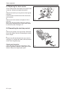
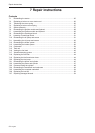
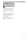
When assembling (see gure 18), pull the cable
ends apart and slide on a thicker shrink tube over
both cables. Then slide on the thinner shrink tubes
over each cable. Connect the cable ends together.
Slide the thinner shrink tubes over the cable ends
and heat the shrink tube rst on both cables sepa-
rately. Slide the thicker shrink tube over the thinner
shrink tubes and then heat the thicker shrink tube.
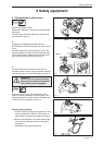
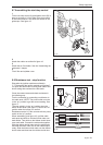
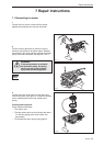
6.7 Assembling the start/stop control
1
Fit the new stop control (A) and tighten screw (B) in
place at a torque of 1 Nm. Slide in the stop control
in the rubber sleeve C and hook the sleeve on the
guide taps. See gure 15.
Fig 15
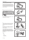
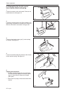
Fig 16
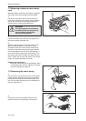
2
Attach the cables as outlined in gure 16.
3
Attach the air lter holder. See the “Assembling the
carburettor” chapter.
4
Fit air lter and cylinder cover.
Fig 18
Fig 17