


42 - English
7.15 Tank unit
Dismantling
1. Drain the fuel from the tank.
2. Remove the cylinder cover, the clutch cover, the
chain and the bar. See the Operator’s Manual.
Dismantle the carburettor as outlined in “Dis-
mantling the carburettor”.
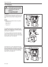
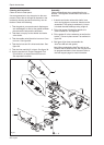
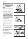
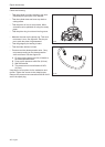
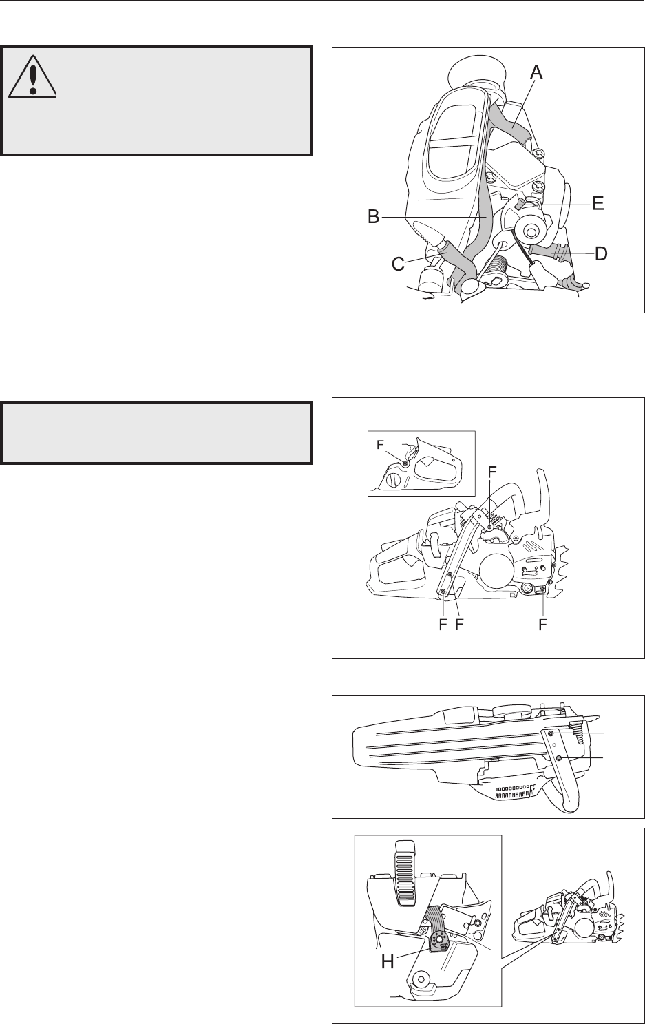
3. Loosen the hoses A to D. See gure 50.
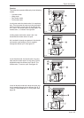
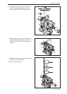
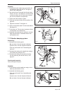
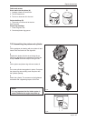
4. Loosen the screws F. See gure 51.
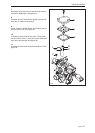
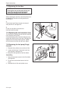
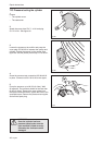
5. Loosen the movement limiter H. See gure 53.
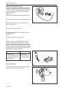
6. Pull out the hoses A to D in the bottom of the car-
burettor compartment. Unhook the throttle cable,
E, from the intake bellows before pulling out from
the bottom of the carburettor compartment.
NOTE!
Exercise care so that the fuel hose and
throttle cable are not damaged.
Repair Instructions
WARNING!
The fuel used in the chain saw has
the following hazardous properties:
1. The fluid and its vapour are poisonous.
2. Can cause skin irritation.
3. Is highly inflammable.
7.16 Venting the fuel tank
The two-way valve has the following properties:
• Controlled opening pressure in both directions,
which prevents a positive pressure or a vacu-
um developing in the fuel tank and impairing
engine performance. This also prevents fuel
leakage.
• Opening pressure outward 100-450 mbar.
• Opening pressure inward (vacuum) max.
70 mbar. (2 locations)
Test
Opening pressure outwards:
1. Open the tank lock and leave it open during the
entire test. Drain the fuel from the tank.
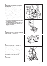
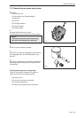
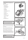
2. Loosen the positive pressure hose as outlined
in gure 54. Connect the pump, ref. no. 531 03
06-23, to the tank valve J.
3. Switch the pump to vacuum mode.
4. After pumping the indicator should be between
10-45 kPa.
Opening pressure inwards:
1. Open the tank lock and leave it open during the
entire test. Drain the fuel from the tank.
2. Loosen the positive pressure hose as
outlined in gure 54. Connect the pump,
ref. no. 531 03 06-23, to the tank valve J.
3. Switch the pump to pressure mode.
4. After pumping the indicator should stop at max.
7 kPa.
Fig 50
Fig 51
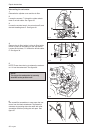
G
G
Fig 53
Fig 52