


English - 29
Repair Instructions
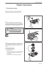
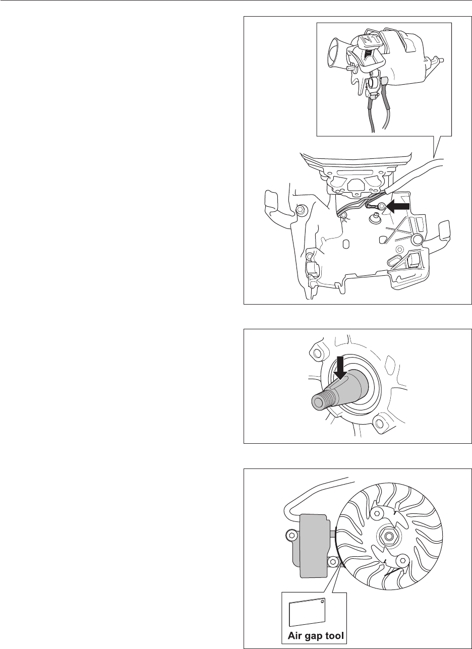
7.7 Assembling the ignition module and
flywheel
1
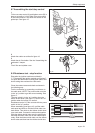
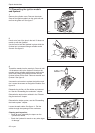
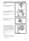
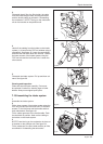
Run the cables through the opening in the crank-
case. Screw the earth cable in place. See gure 11.
Fit the cabling to the stop button.
2
Position the cable channel as outlined in gure 10.
NOTE! Take care that the cable channel is posi-
tioned correctly under the ignition module so that
the cables are not crushed.
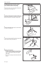
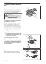
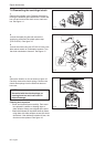
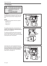
3
Place the ignition module in position. See gure 13.
Do not tighten the screws.
Fig 12
Fig 13
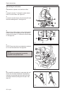
4
Fit the ywheel onto the crankshaft pin. Turn the
ywheel until the key ts into the key slot on the
shaft. See gure 12.
Tighten the screw for the ywheel.
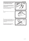
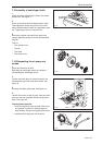
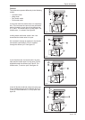
5
Insert the plastic air gap tool, at a thickness of
0.3 +- 0.1 mm, between the lugs on the ignition
module and ywheel. Turn the ywheel so that the
magnets are positioned opposite the ignition mod-
ule. Tighten the screws, at a tightening torque of
4.5- 6 Nm. Remove the plastic air gap tool. Fit the
intake system as outlined in “7.14 Assembling the
intake system”, the tank unit as outlined in “7.16
tank unit”, and the air lter as outlined in “Assem-
bling the carburettor”.
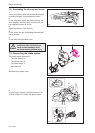
6
Press the ignition lead into the holder on the parti-
tion wall.
7
Then t:
• The air nozzle
• The guide rail and press the cable in place
• the spark plug hat by unscrewing the piston stop.
•
The starter, at a tightening torque of 2.5-3.5 Nm
• The cylinder cover
Fig 11