


• Loose cylinder head bolts.
• Failed cylinder head gasket.
• Burned valves or valve seats.
• Insufficient valve clearance.
• Warped cylinder head.
• Warped valve stem.
• Worn or broken piston ring(s).
• Worn or damaged cylinder bore.
• Broken connecting rod.
• Worn valve seats or valves.
• Worn valve guides.
NOTE: Refer to Engine Service manual No. 0F6923
for further engine service information.
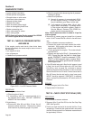
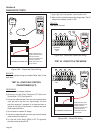
TEST 42 - CHECK OIL PRESSURE SWITCH
AND WIRE 86
If the engine cranks and starts, then shuts down
almost immediately, the cause may be one or more of
the following:
• Low engine oil level.
• Low oil pressure.
• A defective oil pressure switch.
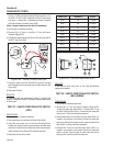
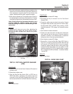
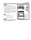
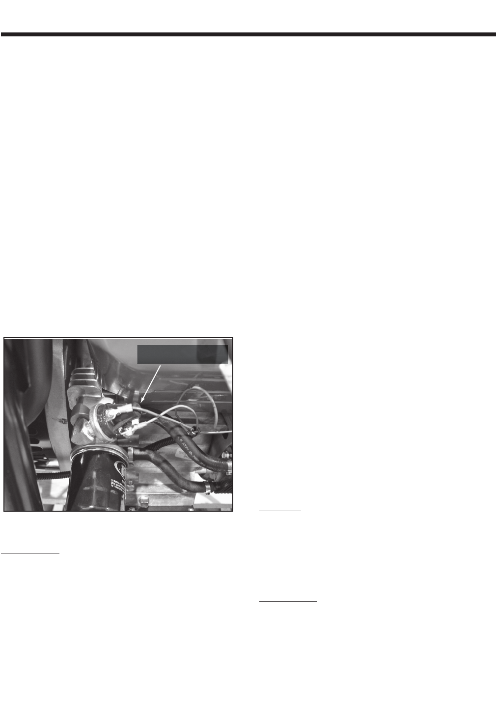
LOW OIL SWITCH
Figure 6-53. – Low Oil Pressure Switch
PROCEDURE:
1. Check engine crankcase oil level.
a. Check engine oil level.
b. If necessary, add the recommended oil to
the dipstick FULL mark. DO NOT OVERFILL
ABOVE THE FULL MARK.
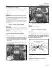
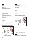
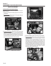
2. Do the following:
a. Disconnect Wire 86 and Wire 0 from the oil
pressure switch terminals. Remove the switch
and install an oil pressure gauge in its place.
b. Start the engine while observing the oil pressure
reading on gauge.
c. Note the oil pressure.
(1) Normal oil pressure is approximately 35-40
psi with engine running. If normal oil pres-
sure is indicated, go to Step 4 of this test.
(2) If oil pressure is below about 10 psi, shut
engine down immediately. A problem exists
in the engine lubrication system. Refer to
Service Manual, Generac P/N 0F6923 for
engine service recommendations.
Note: The oil pressure switch is rated at 10 psi for
v-twin engines.
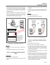
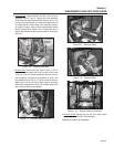
3. Remove the oil pressure gauge and reinstall the oil pressure
switch. Do NOT connect Wire 86 or Wire 0 to the switch termi
-
nals.
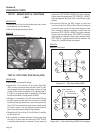
a. Set a voltmeter to measure resistance.
b. Connect the meter test leads across the switch
terminals. With engine shut down, the meter
should read CONTINUITY.
c. Crank and start the engine. The meter should
read INFINITY.
d. Connect one test lead to Wire 0 ( disconnected from
LOP). Connect the other test lead to a clean frame
ground. CONTINUITY should be measured. If
CON-
TINUITY is NOT measured repair or replace Wire 0
between the LOP and the ground terminal connection
on the engine mount.
4. If the LOP switch tests good in Step 3 and oil pressure is good
in Step 2, but the unit still shuts down with a LOP fault, check
Wire 86 for a short to ground. Set a voltmeter to measure
resistance. Disconnect the J2 Connector from the circuit board.
Remove Wire 86 from the LOP switch. Connect one test lead to
Wire 86. Connect the other test lead to a clean frame ground.
INFINITY should be measured. If CONTINUITY is measured,
repair or replace Wire 86 between the LOP switch and the J2
Connector.
RESULTS:
1. If switch tests good, refer to Flow Chart.
2. Replace switch if it fails the test.
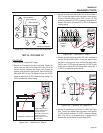
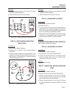
TEST 43 - CHECK START STOP RELAY (SSR)
PROCEDURE:
1. Set a voltmeter to measure resistance.
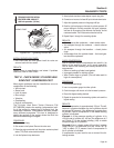
2. Disconnect Wire 15 and Wire 229 from the Start Stop Relay
(SSR). See Figure 6-54.
3. Connect one meter test lead to the terminal that Wire 15 was
removed from. Connect the other meter test lead to the terminal
that Wire 229 was removed from. Resistance measured should
be approximately 100 ohms.
Section 6
DIAGNOSTIC TESTS
Page 60