


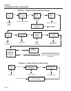
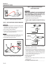
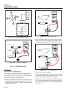
WIRING DIAGRAM
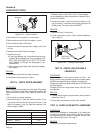
30
86
87a
85
87
85
87a
30
86
87
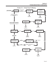
16
15
17
13
16
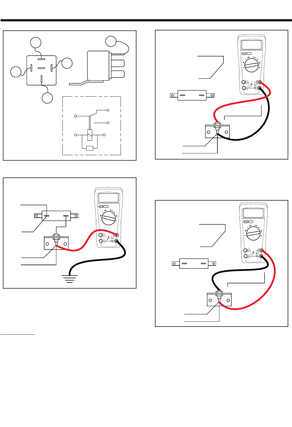
Figure 6-13. – Starter Contactor Relay
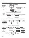
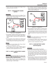
R1
D2
4
14
14
4
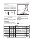
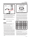
3.0 vdc
Figure 6-14. – Testing Field Boost
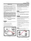
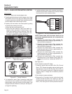
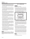
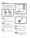
TEST 8 - DIODE/RESISTOR
PROCEDURE:
1. Set volt meter to the diode test range.
2. Disconnect the six pin connector from the Voltage Regulator.
3. Disconnect Connector C1. See Page 17 for connector location.
4. Disconnect both wires from the Resistor (R1).
5. Connect the positive meter test lead to the top terminal of the
diode (D1). Connect the negative meter test lead to the bottom
of the diode (D1). See Figure 6-15. INFINITY or an open condi
-
tion should be measured.
D2
4
14
WIRE 14
REMOVED
14
4
R1
OL
Figure 6-15. – Diode Test Step 5
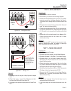
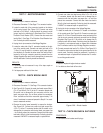
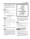
6. Connect the positive meter test lead to the bottom terminal of
the diode (D1). Connect the negative meter test lead to the top
of the diode (D1). Approximately 0.5 Volts should be measured.
D2
4
14
WIRE 14
REMOVED
14
4
R1
.5 vdc
Figure 6-16. – Diode Test Step 6
7. Set volt meter to measure resistance.
8. Connect one meter test lead to the top terminal of the diode
(D1). Connect the other meter test lead to the ground terminal.
INFINITY or an open condition should be measured.
9. Connect one meter test lead to one terminal of the resistor
(R1). Connect the other meter lead to the remaining terminal of
resistor (R1). See Figure 6-17. Approximately 25 ohms should
be measured.
Section 6
DIAGNOSTIC TESTS
Page 42