


Section 6
DIAGNOSTIC TESTS
Page 57
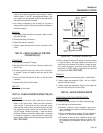
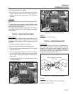
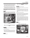
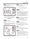
9. Now check the flywheel magnet by holding a screwdriver at the
extreme end of its handle and with its point down. When the tip
of the screwdriver is moved to within 3/4 inch (19mm) of the
magnet, the blade should be pulled in against the magnet.
10. Now check the flywheel key. The flywheel’s taper is locked on
the crankshaft taper by the torque of the flywheel nut. A keyway
is provided for alignment only and theoretically carries no load.
Note: If the flywheel key becomes sheared or even
partially sheared, ignition timing can change.
Incorrect timing can result in hard starting or fail-
ure to start.
RESULTS:
If sparking still does not occur after adjusting the
armature air gap, testing the ground wires and per-
forming the basic flywheel test, replace the ignition
magneto(s).
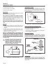
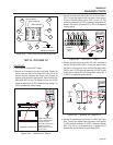
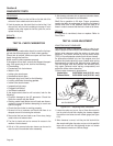
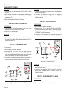
0.008-0.012" GAUGE
(0.203-0.304 mm)
MAGNETO
Figure 6-49. – Setting Ignition Magneto (Armature)
Air Gap
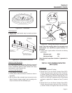
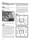
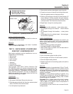
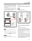
TEST 36 - TEST FUEL SHUTOFF SOLENOID
(FSS)
PROCEDURE
1. Disconnect Wire 16 from the Starter Contactor (SC) located on
the starter motor.
2. Remove the air cleaner cover.
3. Place the Start-Run-Stop Switch (SW1) to STOP then to
START. When SW1 is activated a click should be heard and
or activation of the Fuel Shutoff Solenoid should be felt. It can
then be assumed that the Fuel Shutoff Solenoid is functioning.
RESULTS:
Refer to flow chart.
TEST 37: TEST FUEL SHUTOFF SOLENOID
VOLTAGE
PROCEDURE:
1. Set a voltmeter to measure DC voltage.
2. Disconnect the two pin connector from the Fuel Shutoff
Solenoid (FSS).
3. Connect the positive meter test lead to the red wire. Connect
the negative meter test lead to the black wire. Place the Start-
Run-Stop switch (SW1) to START. During cranking, 12 VDC
should be measured. If DC voltage is not measured continue
testing.
4. Set a voltmeter to measure resistance.
5. Connect one meter test lead to the black wire. Connect the
other meter test lead to frame ground. Continuity should be
measured. If continuity is not measured repair or replace the
black ground wire or correct poor ground connection.
6. Set a voltmeter to measure DC voltage.
7. Remove Wire 14 from the Start-Stop Relay (SSR). Refer to
Figure 6-41 on Page 54. Connect the positive meter test lead
to the terminal of the SSR that Wire 14 was just removed.
Connect the negative meter test lead to frame ground. Place
the Start-Run-Stop Switch (SW1) to the start position. 12 VDC
should be measured. If 12 VDC is measured repair or replace
Wire 14 between the SSR and Resistor 1 or between Resistor
1 and the FSS.
RESULTS:
Refer to flow chart.
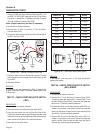
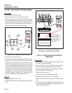
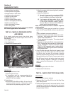
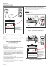
TEST 38 - CHECK FUEL PUMP
FUEL PUMP
FUEL TO
CARBURETOR
FUEL FROM TANK
PULSE LINE
Figure 6-50. – Fuel Pump and Fuel Lines