


Section 6
DIAGNOSTIC TESTS
Page 52
Ground. 12 VDC should be measured. Reconnect Wire 13 to
the SCR. If 12 VDC is NOT measured on Wire 13 Stop Testing
and repair or replace Wire 13 between the Starter Contactor
(SC) and the Starter Contactor Relay (SCR).
Note: Jumper leads may be used if necessary.
4. Set voltmeter to measure resistance.
5. Remove Wire 13, Wire 16, and Wire 17 from the Starter
Contactor Relay (SCR)
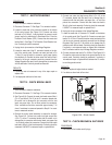
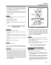
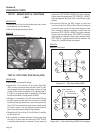
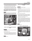
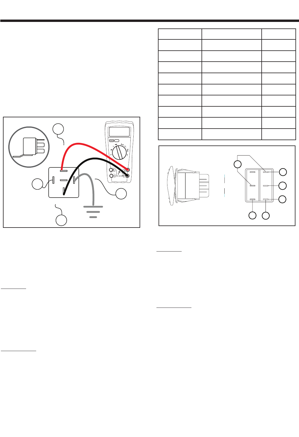
6. Connect the meter leads across Terminal 87 and Terminal 30 of
the SCR. See Figure 6-35.
85
87a
30
86
SCR
87
16
15
17
13
00.00
Figure 6-35. – Starter Contactor Relay Test
7. Connect a jumper wire from Terminal 85 to ground. The relay
should energize and the voltmeter should read continuity. See
Figure 6-35.
8. Reconnect all Wires.
RESULTS:
If continuity was not measured in Step 7 replace the
Starter Contactor Relay. If all steps passed refer back
to flow chart.
TEST 27 - CHECK START-RUN-STOP SWITCH
(SW1)
PROCEDURE:
1. Set a voltmeter to measure resistance.
2. Remove all wires from the Start-Run-Stop Switch (SW1).
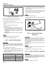
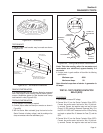
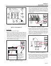
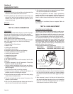
3. Using the chart below ohm out the Start-Run-Stop Switch.
Connect one meter test lead to one terminal and the other meter
test lead to the other terminal. With meter leads connected acti
-
vate the switch to Start, Stop or Run and follow the chart.
4. Reconnect all wires to the switch.
CONDITION TERMINALS RESULT
STOP 5,4 OPEN
STOP 5,6 CLOSED
STOP 2,1 OPEN
STOP 2,3 CLOSED
RUN ALL CONDITIONS OPEN
START 5,4 CLOSED
START 5,6 OPEN
START 2,1 CLOSED
START 2,3 OPEN
167
STOP
0
15
15
17
4
5
6
1
2
3
RUN
START
0
Figure 6-36. – Start-Run-Stop Switch (SW1)
RESULTS:
If the switch fails any part of the test procedure
replace the switch.
TEST 28 - CHECK START-RUN-STOP SWITCH
(SW1) WIRING
PROCEDURE:
1. Set voltmeter to measure resistance.
2. Remove Wire 17 from the Starter Contactor Relay (SCR).
Connect one meter test lead to Wire 17. Remove Wire 17 from
the Start-Run-Stop Switch (SW1). Connect the other meter test
lead to wire 17. Continuity should be measured.
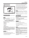
3. Remove both Wire 0 from the Start-Run-Stop switch (SW1) it is
located in two positions on the switch. Connect one meter test
lead to one Wire 0 and connect the other meter test lead to the
other Wire 0. Continuity should be measured.
4. Remove Wire 0 from the Start-Run-Stop switch (SW1) it is
located in two positions on the switch. Connect one meter test
lead to one Wire 0 and connect the other meter test lead to
frame ground. Continuity should be measured.