


Section 3
DESCRIPTION & COMPONENTS
INTRODUCTION
The generator revolving field (rotor) is driven by an
air-cooled engine at about 3600 rpm.
The generator may be used to supply electrical power
for the operation of 120 and/or 240 volts, 1-phase, 60
Hz, AC loads.
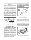
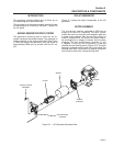
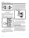
ENGINE-GENERATOR DRIVE SYSTEM
The generator revolving field is driven by an air-
cooled, horizontal crankshaft engine. The generator is
directly coupled to the engine crankshaft (see Figure
1). Both the engine and generator rotor are driven at
approximately 3600 rpm, to provide a 60 Hz AC out-
put.
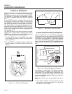
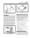
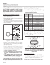
THE AC GENERATOR
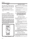
Figure 3-1 shows the major components of the AC
generator.
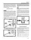
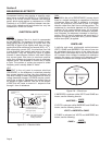
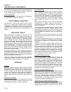
ROTOR ASSEMBLY
The 2-pole rotor must be operated at 3600 rpm to
supply a 60 Hertz AC frequency. The term “2-pole”
means the rotor has a single north magnetic pole and
a single south magnetic pole. As the rotor rotates, its
lines of magnetic flux cut across the stator assem-
bly windings and a voltage is induced into the stator
windings. The rotor shaft mounts a positive (+) and
a negative (-) slip ring, with the positive (+) slip ring
nearest the rear bearing carrier (Figure 3-2). The rotor
bearing is pressed onto the end of the rotor shaft. The
tapered rotor shaft is mounted to a tapered crankshaft
and is held in place with a single through bolt.
Page 9
STATOR
ENGINE
ENGINE
ADAPTOR
REAR BEARING
CARRIER
BRUSH HOLDER
ASSEMBLY
ROTOR
Figure 3-1. – AC Generator Exploded View