


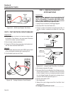
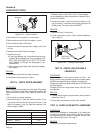
12. Connect the meter test leads across Stator lead 2 (Pin 6) at
the C1 connector female side and frame ground. Be careful not
to damage the pin connectors with the test leads, use paper
clips - do not force probes into connectors. See Figure 6-18.
INFINITY should be read.
13. Connect the meter test leads across Stator lead 66 (Pin 9) at
the C1 connector female side and frame ground. Be careful not
to damage the pin connectors with the test leads, use paper
clips - do not force probes into connectors. See Figure 6-18.
INFINITY should be read.
14. Connect the meter test leads across Stator leads Wire 11 and
Stator lead 66A (Pin 4) at the C1 connector female side. Be
careful not to damage the pin connectors with the test leads,
use paper clips - do not force probes into connectors. See
Figure 6-18. INFINITY should be read.
15. Connect the meter test leads across Stator leads Wire 11 and
Stator lead 2 (Pin 6) at the C1 connector female side. Be care
-
ful not to damage the pin connectors with the test leads, use
paper clips - do not force probes into connectors. See Figure
6-18. INFINITY should be read.
16. Connect the meter test leads across Stator leads Wire 11 and
Stator lead 66 (Pin 9) at the C1 connector female side. Be care
-
ful not to damage the pin connectors with the test leads, use
paper clips - do not force probes into connectors. See Figure
6-18. INFINITY should be read.
17. Connect the meter test leads across Stator lead 66A (Pin 4)
and Stator lead 2 (Pin 6) at the C1 connector female side. Be
careful not to damage the pin connectors with the test leads,
use paper clips - do not force probes into connectors. See
Figure 6-18. INFINITY should be read.
18. Connect the meter test leads across Stator lead 66A (Pin 4)
and Stator lead 66 (Pin 9) at the C1 connector female side. Be
careful not to damage the pin connectors with the test leads,
use paper clips - do not force probes into connectors. See
Figure 6-18. INFINITY should be read.
19. Connect the meter test leads across Stator lead 2 (Pin 6) and
Stator lead 66 (Pin 9) at the C1 connector female side. Be care
-
ful not to damage the pin connectors with the test leads, use
paper clips - do not force probes into connectors. See Figure
6-18. INFINITY should be read.
RESULTS:
If the stator fails any step replace it, for Steps 1-10
keep in mind resistance values may vary depending
on ambient temperature and calibration of the meter
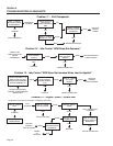
used. If the stator passes all tests refer back to the
flow chart.
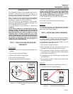
TEST 10 - SENSING LEADS
PROCEDURE:
1. Set a VOM to measure resistance.
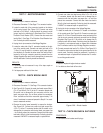
2. Disconnect Connector C1. See Page 17 for connector location.
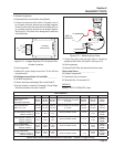
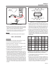
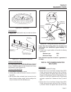
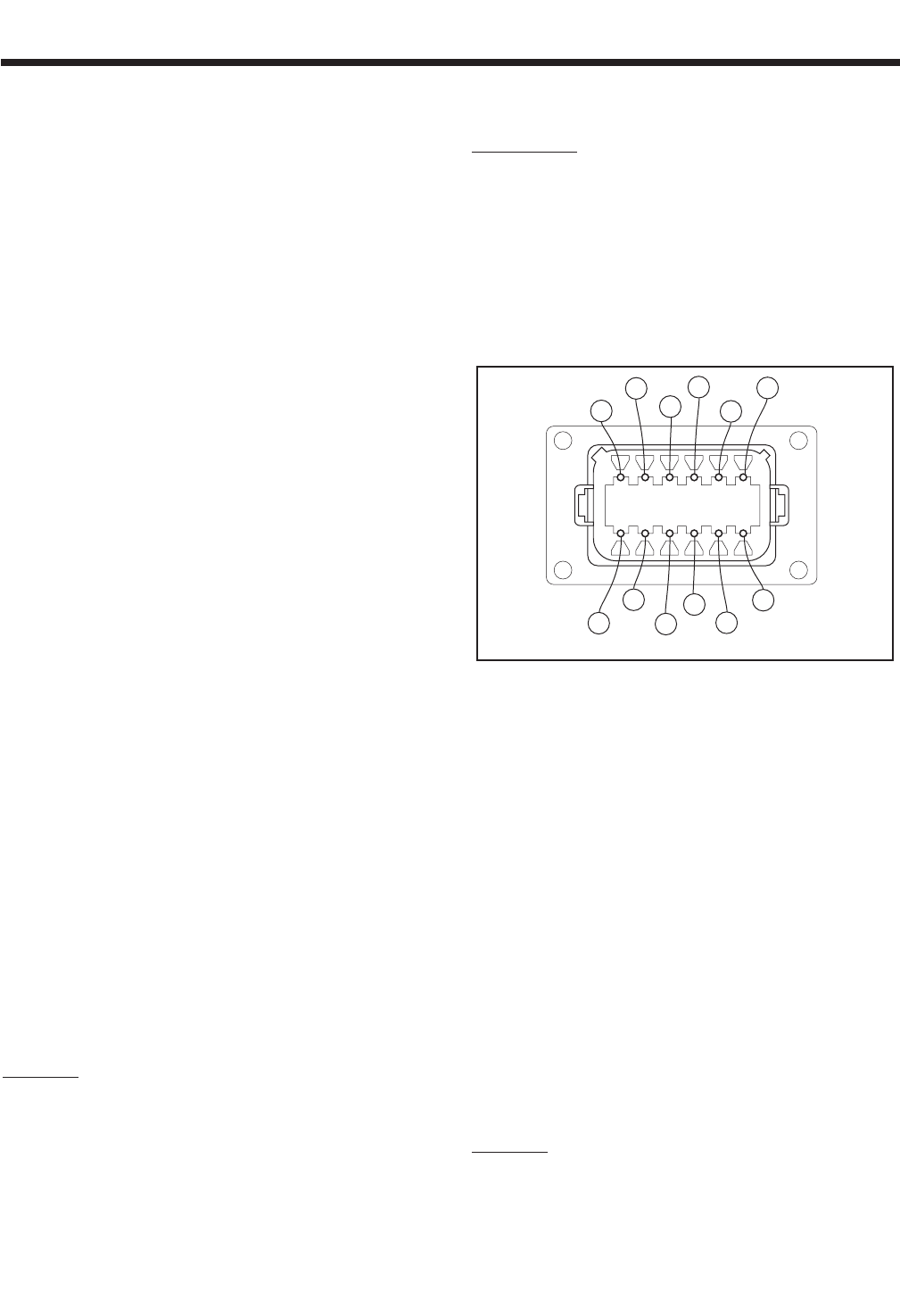
3. Locate the male side of the connector located on the bottom of
the control panel. See Figure 6-19. Connect one meter test lead
to Pin 1 Wire 11S. It may be helpful to connect a small jumper
lead to the individual pin. Connect the other meter test lead to
Wire 11S at Terminal Block 2 (TB2) . See Page 17 for Terminal
Block 2 location. Continuity should be measured.
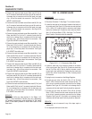
PIN
LOCATION
7
PIN
LOCATION
6
PIN
LOCATION
12
PIN
LOCATION
1
0
4
77
66
55
6
2
77A
66A
55A
44S
11S
Figure 6-19. – C1 Connector, Male Side
4. Locate the male side of the connector located on the bottom
of the control panel. See Figure 6-19. Connect one meter test
lead to Pin 2 Wire 44S. It may be helpful to connect a small
jumper lead to the individual pin. Connect the other meter test
lead to Wire 44S at Terminal Block 2 (TB2). Continuity should
be measured.
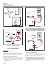
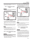
5. Unplug the six pin connector at the Voltage Regulator.
6. Connect the one meter test lead to Wire 11S at Terminal
Block 2 (TB2). Connect the other meter test lead to Wire 11S
at the six pin connector previously removed from the Voltage
Regulator. See Figure 6-11. Be careful not to damage the pin
connectors with the test leads. Continuity should be measured.
7. Connect the one meter test lead to Wire 44S at Terminal
Block 2 (TB2). Connect the other meter test lead to Wire 44S
at the six pin connector previously removed from the Voltage
Regulator. See Figure 6-11. Be careful not to damage the pin
connectors with the test leads. Continuity should be measured.
RESULTS:
1. If continuity was not measured in any of the steps repair or
replace wire.
2. If all steps pass refer back to flow chart.
Section 6
DIAGNOSTIC TESTS
Page 44