


00.00
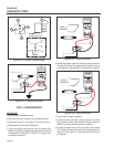
C.B.
20/30A
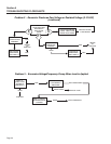
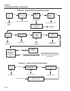
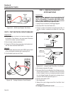
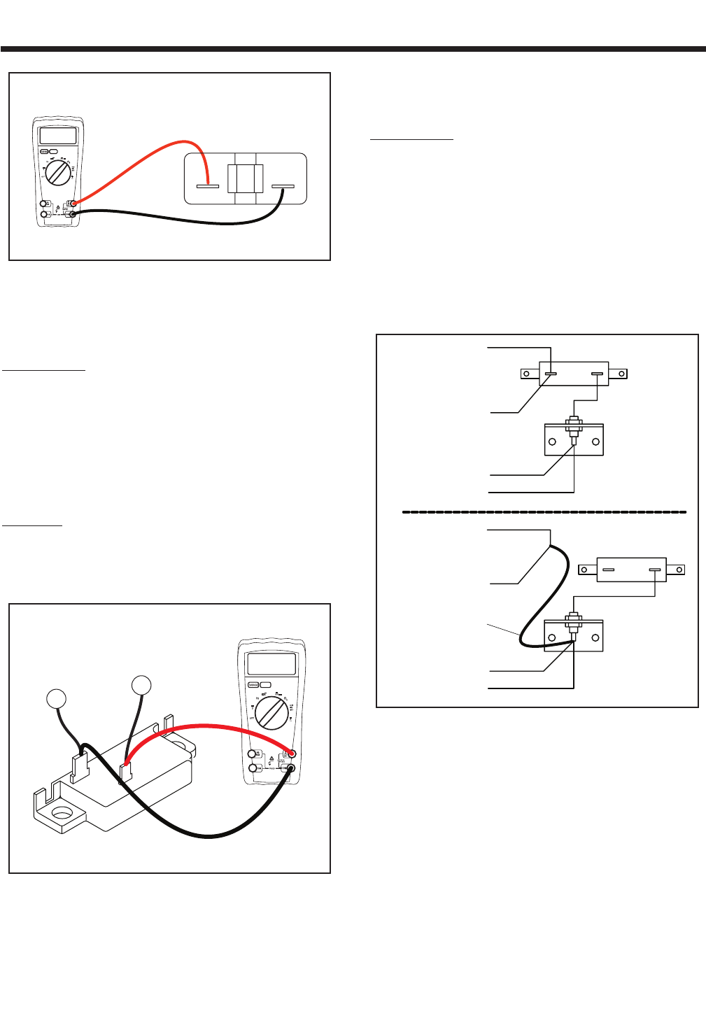
Figure 6-8. – 20/30 Amp Breaker Test Points
TEST 3 - TEST EXCITATION CIRCUIT BREAKER
PROCEDURE:
1. With the generator shut down for at least two minutes, locate
the Excitation Circuit Breaker in the control panel. Disconnect
wires from the breaker, to prevent interaction.
2. Set a volt meter to measure resistance.
3. Connect the VOM test probes across the circuit breaker termi
-
nals. The meter should read CONTINUITY.
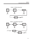
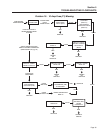
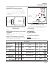
RESULTS:
1. If circuit breaker tests bad (meter reads “OPEN”) then proceed
to Test 4 and replace the breaker after completing Test 4.
2. If circuit breaker is good, go on to Test 4.
2
162
00.00
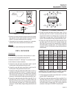
Figure 6-9. - Testing Excitation Circuit Breaker
TEST 4 - FIXED EXCITATION TEST/
ROTOR AMP DRAW
PROCEDURE:
*NOTE: If the generator is not producing AC
Power, loss of governor control may occur caus-
ing an overspeed or extremely high RPM condi-
tion. If this condition occurs manually control
throttle (60Hz /3600 RPM) to perform test.
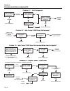
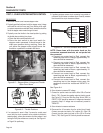
1. Unplug the six pin connector at the Voltage Regulator.
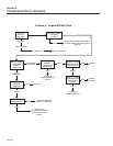
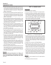
2. Disconnect Wire 14 from the Resistor (R1).
3. Connect a jumper wire between the removed end of Wire 14
and Wire 4 where it is soldered at the Diode (D1). See Figure
6-10.
R1
D2
4
14
14
4
D2
4
14
WIRE 14
REMOVED
JUMPER LEAD
14
4
R1
Figure 6-10. – Jumper Lead From Wire 14 to Diode
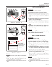
4. Set voltmeter to measure AC voltage
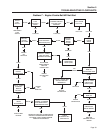
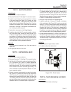
5. Disconnect Wire 2 from the Excitation Circuit Breaker and con
-
nect one meter test lead to it. Connect the other meter test lead
to Wire 6 located in the six pin connector previously removed
from the Voltage Regulator. Be careful not to damage the pin
connectors with the test leads. See Figure 6-11.
6. Set Idle control switch to OFF.
7. Start the generator.
8. Measure the output voltage across Wire 2 and Wire 6 and
record the results.
AC Voltage across Wires 2 and 6 = _____________
Section 6
DIAGNOSTIC TESTS
Page 38