


Section 1
GENERATOR FUNDAMENTALS
A SIMPLE AC GENERATOR
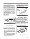
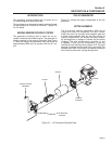
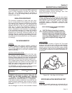
Figure 1-4 shows a very simple AC Generator. The
generator consists of a rotating magnetic field called a
ROTOR and a stationary coil of wire called a STATOR.
The ROTOR is a permanent magnet which consists
of a SOUTH magnetic pole and a NORTH magnetic
pole.
As the MOTOR turns, its magnetic field cuts across
the stationary STATOR. A voltage is induced Into
the STATOR windings. When the magnet's NORTH
pole passes the STATOR, current flows in one direc-
tion. Current flows in the opposite direction when the
magnet's SOUTH pole passes the STATOR. This con-
stant reversal of current flow results in an alternating
current (AC) waveform that can be diagrammed as
shown in Figure 1-5.
The ROTOR may be a 2-pole type having a single
NORTH and a single SOUTH magnetic pole. Some
ROTORS are 4-pole type with two SOUTH and two
NORTH magnetic poles. The following apply:
1. The 2-pole ROTOR must be turned at 3600 rpm to produce
an AC frequency of 60 Hertz, or at 3000 rpm to deliver an AC
frequency of 50 Hertz.
2. The 4-pole ROTOR must operate at 1800 rpm to deliver a 60
Hertz AC frequency or at 1500 rpm to deliver a 50 Hertz AC
frequency.
S
TAT
O
R
R
O
T
OR
MA
G
NETI
C
FIEL
D
Figure 1-4. – A Simple AC Generator
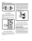
CURRENT
VOLTAGE
ONE CYCLE
0
180
360
(+)
(-)
Figure 1-5. – Alternating Current Sine Wave
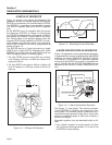
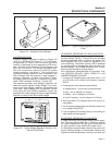
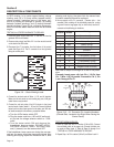
A MORE SOPHISTICATED AC GENERATOR
Figure 1-6 represents a more sophisticated generator.
A regulated direct current is delivered into the ROTOR
windings via carbon BRUSHES AND SLIP RINGS.
This results in the creation of a regulated magnetic
field around the ROTOR. As a result, a regulated volt-
age is induced into the STATOR. Regulated current
delivered to the ROTOR is called “EXCITATION” cur-
rent.
S
TAT
OR
BR
US
HE
S
12
0
V
12
0
V
S
LI
P
RIN
GS
AC
OU
TP
U
T
DC
CU
RRENT
S
TAT
OR
24
0
V
Figure 1-6. – A More Sophisticated Generator
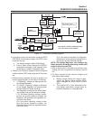
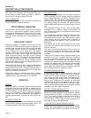
See Figure 1-7 (next page). The revolving magnet-
ic field (ROTOR) is driven by the engine at a con-
stant speed. This constant speed is maintained by a
mechanical engine governor. Units with a 2-pole rotor
require an operating speed of 3600 rpm to deliver a
60 Hertz AC output.
Generator operation may be described briefly as fol-
lows:
1. Some “residual” magnetism is normally present in the Rotor
and is sufficient to induce approximately 7 to 12 volts AC Into
the STATOR's AC power windings.
Page 4