


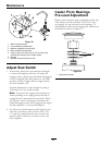

Maintenance
1. This adjustment must be made with the drive
wheels turning. First raise the frame and block up
so that drive wheels can rotate freely.
2. Remove the electrical connection from the seat
safety switch, located directly to the left of the seat
switch assembly beside the hydraulic oil reservoir.
3. Temporarily install a jumper wire across the
terminals in the connector of the main wiring
harness.
4. Run the unit at least 5 minutes with the drive
levers at full forward speed to bring hydraulic
system oil up to operating temperature.
5. Unhook seat latch and tilt seat forward.
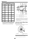
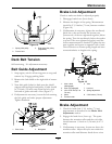
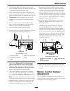
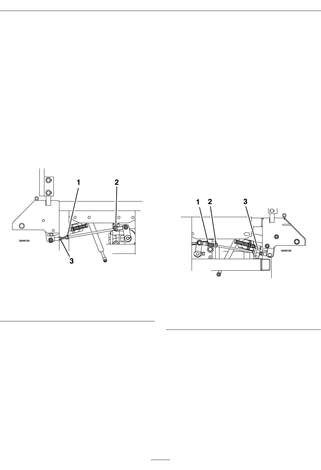
6. Loosen lock nuts from the ball joints at each end
of the pump control linkage (Figure 20).
Figure 20
Left-Hand Side of Unit
1. Turn here to adjust
3. Loosen here (right-hand
thread)
2. Loosen here (left-hand
thread)
7. Start engine. Brake must be engaged and
motion control levers out to start engine.
Operator does not have to be in the seat
because of the jumper wire being used.Run
engine at full throttle and release brake.
8. The reverse indicator spring must be correct
before the following adjustments can be made.
See the Reverse Indicator Adjustment section.
Note: The motion control lever needs to be in
neutral while making any necessary adjustments.
9. Bring the motion control lever into the neutral
position. Adjust pump control rod length by
rotating the double nuts on the rod in the
appropriate direction until the wheels slightly
creep in reverse (Figure 20). Move the motion
control lever to the reverse position and while
applying slight pressure to the lever allow the
reverse indicator spring to bring the levers back to
neutral. The wheel must stop turning or slightly
creep in reverse. When adjustment is complete,
tighten lock nuts onto ball joints.
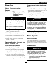
10. Adjustment for the RH motion control lever:
Bring the RH motion control lever into the
neutral position.
Adjust the RH pump control rod length by
rotating the double nuts on the rod in the
appropriate direction until the wheels slightly
creep in reverse. Move the motion control lever
to the reverse position and while applying slight
pressure to the lever allow the reverse indicator
spring to bring the levers back to neutral. The
wheel must stop turning or slightly creep in
reverse (Figure 21).
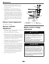
Figure 21
Right-Hand Side of Unit
1. Loosen here (right-hand
thread)
3. Loosen here (left-hand
thread)
2. Turn here to adjust
11. Shut off unit. Remove jumper wire from wire
harness connector and plug connector into seat
switch.
Motion Control Damper
Adjustment
The top damper mounting bolt can be adjusted to
obtain a more desired motion control lever resistance.
See Figure 22 for mounting options.
37