


Maintenance
all the chains is approximately equal. Make sure
all chain attachment bolts are tight. Reposition
anti-scalp rollers and tighten securely.
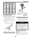
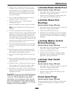
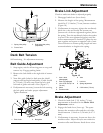
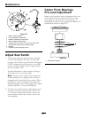
Figure 14
1. Apply downward pressure here
2. Place locking pliers here to hold spring
3. 10 1/2 inches (26.7 cm)
4. Remove force on deck springs by loosening nuts here
5. Swivel
6. Front of unit
7. Socket head adjusting screw
8. Jam nut
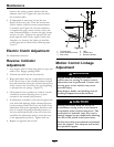
12. Raise deck lift lever to the 5 inch (12.7 cm)
cutting height position (Figure 8). Adjust spring
compression until proper distance is obtained
between the two large washers (Figure 14).
Adjustment is made by turning the nut at the
front of each spring (clockwise will shorten the
spring, counterclockwise will lengthen the spring).
Lock in position with jam nuts.
Note: When above adjustments have been made,
the front of the deck will be slightly lower than the
rear of the deck.
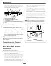
Pump Drive Belt Tension
Self-tensioning - No adjustment necessary.
Mule Drive Belt Tension
Adjustment
Self-tensioning idler, adjust as follows:
1. Stop engine, wait for all moving parts to stop, and
remove key. Engage parking brake.
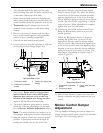
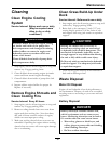
2. Check to make sure the center of the bolt head
in the center of the spring loaded pulley, on left
side engine deck support, is positioned between
the centers of the two alignment holes in the
left support plate (Figure 15 and Figure 16). It
is necessary to adjust the belt tension when the
center of the bolt head is at or below the center
of the bottom alignment hole.
3. When adjustment is necessary, loosen the idler
pulley on the right-hand side so it can move up
and down in the slot.
Place a wrench on the 3/8 inch nut in the center
of the spring loaded pulley and apply upward
pressure to relieve tension on the spring (a 1/2
inch drive breaker bar and 9/16 inch socket works
best).
Reposition the adjusting pulley to the bottom of
the slot.
Note: When installing a new belt, it is necessary
to reposition the right adjusting pulley upward in
the slot in order to position the center of the spring
loaded pulley between the alignment holes.
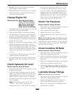
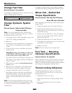
Figure 15
1. Front of unit
2. Alignment holes
34