


Maintenance
• Caster wheel spacer nuts.
• Fuel tank bulkhead tting nuts.
Adhesives such as “Loctite RC/609 or RC/680” or
“Fel-Pro Pro-Lock Retaining I or Retaining II” are
used on the following:
Fuel tank studs, where studs are inserted into tank.
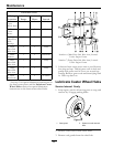
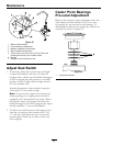
Mobil HTS Grease (Or
Food-Grade Anti-seize)
Mobil HTS grease (or food-grade anti-seize) is used
in the following locations:
• Between the cutter housing spindle and bearings.
• Between the jackshaft and bearings and the
jackshaft and sheaves.
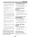
Copper-Based Anti-seize
Copper-based anti-seize is used in the following
location:
On threads of Blade Bolts. See Check Mower
Blades section.
Dielectric Grease
Dielectric grease is used on all blade type electrical
connections to prevent corrosion and loss of contact.
Adjustments
Note: Disengage PTO, shut off engine, wait for
all moving parts to stop, engage parking brake, and
remove key before servicing, cleaning, or making any
adjustments to the unit.
Deck Leveling
1. Position mower on a at surface.
2. Stop engine, wait for all moving parts to stop, and
remove key. Engage parking brake.
3. Check tire pressure in drive tires. Proper ination
pressure for tires is 13 psi (90 kPa). Proper
ination pressure for tires is 13 psi (90 kPa).
Adjust if necessary.
4. Set anti-scalp rollers to top holes or remove them
completely for this adjustment.
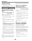
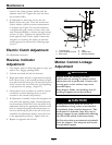
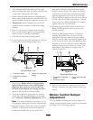
5. Raise the deck to the 5 inch (12.7 cm) height
position (also transport position) and take all force
off of the two large deck lift springs by loosening
the nuts at the front of each spring (Figure 14).
6. Lower the deck to the 1 1/2 inch (3.81 cm) height
position.
7. Place a 3/4 inch (19 mm) thick block of wood
under each of the two rear anti- scalp roller
brackets and place one under one of the front
center anti-scalp roller brackets.
8. Loosen the two top chain bolts in slots in the rear
deck lift arms. Loosen jam nuts and back off the
socket head adjusting screws on the bottom of
the arms until the chains are just loose. Turn the
socket head adjusting screws in until slack is taken
out of each chain. Tighten the jam nuts. Tighten
the chain bolts in the deck lift arms making sure
they don’t move while tightening.
9. Loosen the four nuts which secure the front
swivels (two per side) until the front chains are
loose and front of deck is supported by the 3/4
inch (19 mm) block. Do Not loosen the front
chain hardware.
10. On left side, adjust front swivel using the locking
nut behind the swivel until the front chain is tight
and all slack is removed from linkage. Do Not lift
front of deck off 3/4 inch (19 mm) block. Secure
front swivel using locking nut in front of swivel.
Repeat for right side.
11. Recheck that the 3/4 inch (19 mm) blocks t just
snugly under the brackets and that the tension on
33