


8
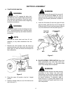
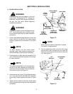
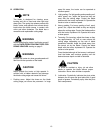
5. While holding the flat weld nut (17) in position,
place the cable trigger housing under the blade
pivot handle (6) and fasten with the oval hd. cntsk.
screw (18). See Figure 8.
Figure 8
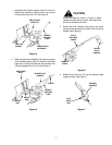
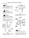
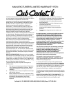
NOTE
When installing the center cable tie, make
certain it is positioned far enough from the
support tube eyelet to prevent the cable from
binding on the eyelet when the blade pivot
handle is moved to either of the angled
positions.
6. Secure the blade release cable to the pivot handle
with the three tie straps (19) as shown in Figure 9.
Cut excess from tie strap ends.
Figure 9
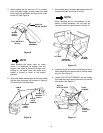
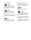
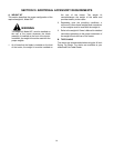
7. If not already done, screw the adjustment clevis (4)
onto the threaded end of the lift rod (3).
NOTE
When attaching the lift rod assembly to the
blade’s A-frame assembly, the rod must be
inserted from left to right as shown in Figure 10.
Figure 10
8. Install the lift rod (3) in the front lift bracket of the A-
frame assembly and secure with an internal cotter
pin (14). See Figure 10.
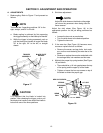
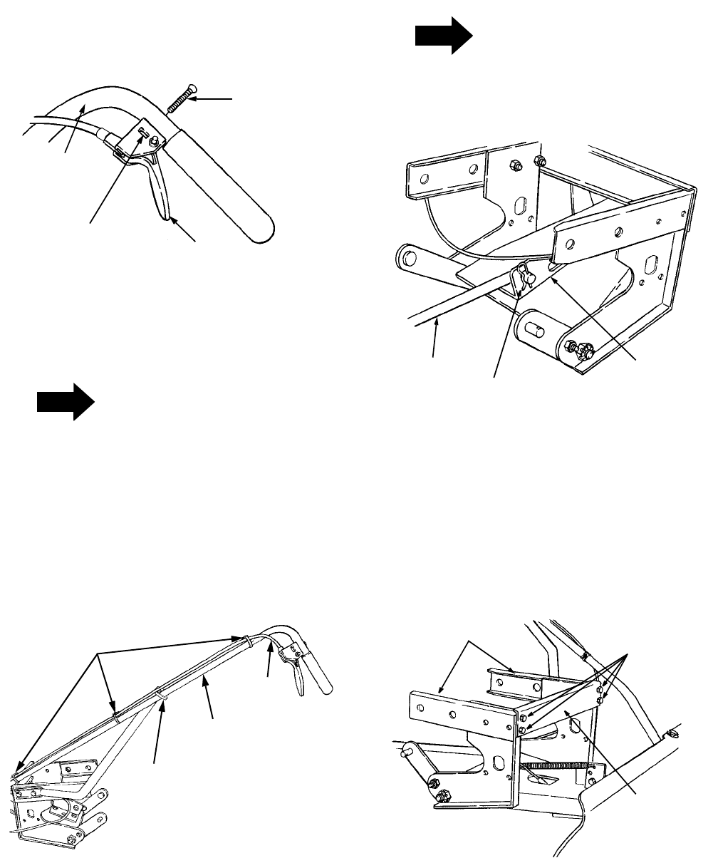
9. Loosen, BUT DO NOT REMOVE, the four screws
that fasten the front support plate to the LH and RH
hitch plates. See Figure 11.
Figure 11
OVAL HD.
CNTSK. SCREW
TRIGGER
ASSEMBLY
BLADE
PIVOT
HANDLE
FLAT WELD NUT
IN SLOT
BLADE
PIVOT
HANDLE
BLADE
RELEASE
CABLE
CABLE
TIE
SUPPORT
TUBE
EYELET
LIFT ROD
INTERNAL
COTTER PIN
BLADE
A-FRAME
FOUR
SCREWS
FRONT
SUPPORT
PLATE
RH & LH
PLATESHITCH