


11
B. BLADE REATTACHMENT
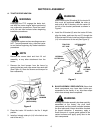
WARNING
Place the tractor and front blade on a firm and
level surface. Disengage the PTO, engage the
brake lock, stop the tractor engine and remove
the key from the switch before beginning
installation procedures.
WARNING
The exhaust system and surrounding areas are
HOT. To avoid personal injury, allow the tractor
to cool before beginning any blade installation
procedures.
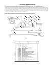
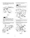
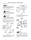
1. Position the blade assembly directly in front of the
tractor with the LH and RH hitch plate channel
brackets aligned with the channels of the tractor
frame.
NOTE
To ease insertion into the tractor frame
channels, apply a light coating of grease to the
channel brackets of the blade hitch assembly.
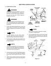
2. Slide the blade hitch assembly into the tractor
frame channels. Refer to Figure 12.
3. Secure the blade hitch assembly to the tractor
frame channels using the hex cap screws (10) and
belleville washers (11). Refer to Figure 12.
NOTE
The tractor’s implement lift handle must be
placed in the No. 2 height position.
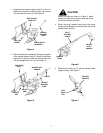
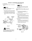
CAUTION
When installing the lift bracket (8), the tractor lift
links must be positioned within the slots at
each side of the lift bracket, with the center lift
rod tab of the bracket positioned as shown in
Figure 3.
4. Fasten the lift bracket (8) onto the implement lift
links by sliding the rod (7) through the bracket and
links, and secure with the internal cotter pin (14).
Refer to Figure 3.
5. Attach the adjustment clevis (4) to the lift bracket
(8) by aligning the holes and inserting the clevis pin
(9). Secure with the internal cotter pin (14). Refer
to Figure 13.