


Yournewtractorhasbeenassembledatthefactorywithexceptionofthosepartsleft
unassembledfor shippingpurposes.To ensuresafe and properoperationof your
tractorall partsand hardwareyou assemblemustbe tightenedsecurely.Use the
correcttoolsas necessaryto insurepropertightness.Reviewthe videocassettebefore
you begin.
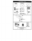
TOOLS REQUIRED FOR ASSEMBLY
A socketwrenchset willmakeassembly
easier. Standardwrenchsizesyou need
are listedbelow.
(1) 9/16" wrench (1) Pliers
(2) 1/2"wrench (1) Utilityknife
(1) Tire pressuregauge
When rightor lefthandis mentionedin
thismanual,itmeans,from yourpointof
• view,when youare in the operating
position(seated behindthe steering
:iII wheel).
TO REMOVETRACTOR FROM
CARTON
UNPACK CARTON
I. Removeall accessiblelooseparts
and partscartons from carton.
2. Cut,fromtopto bottom,alonglines on
allfourcomers of carton,and lay
panelsflat.
3. Checkfor any additionallooseparts
orcartonsand remove,
BEFORE REMOVINGTRACTOR
FROM SKID
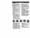
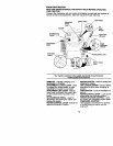
A'I-rACH STEERING WHEEL
ASSEMBLE EXTENSION SHAFT AND
BOOT
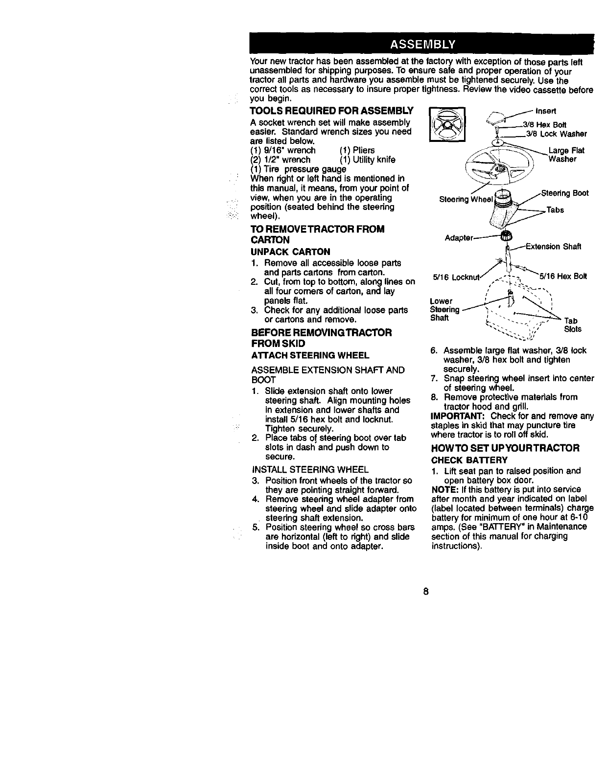
1. Slideextensionshaftonto lower
steeringshaft. Alignmountingholes
inextensionand lower shaftsand
install5/16 hexboltand Iocknut.
Tightensecurely.
2. Placetabsof,steedngbootover tab
slotsin dashand pushdownto
secure.
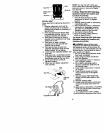
INSTALLSTEERING WHEEL
3. Positionfrontwheelsofthe tractorso
theyare pointingstraightforward.
4. Remove steeringwheel adapterfrom
steeringwheel and slide adapteronto
steeringshaftextension.
5. Positionsteeringwheel so crossbars
are horizontal(leftto right)and slide
insideboot and ontoadapter.
_ Insert
_" 3/8Hex Bolt
!_-----"3/8 LockWasher
__La_ge Flat
S g Boot
Shaft
5/16
Lower '_ "'
Steering ,..
Shaft ' "-
Tab
Slots
6. Assemble large flat washer, 3/8 lock
washer, 3/8 hex bolt and tighten
securely.
7. Snap steering wheel insert into center
of steering wheel.
9. Remove protective materials from
tractor hood and gdll.
IMPORTANT: Check for and remove any
staples in skid that may puncture tire
where tractor is to rolloff skid.
HOWTO SET UPYOURTRACTOR
CHECK BA'n'ERY
1. Lift seat pan to raised position and
open battery box door.
NOTE: If this battery is put into service
after month and year indicated on label
(label located between terminals) charge
battery for minimum of one hour at 6-10
amps. (See "BATTERY" in Maintenance
section of this manual for charging
instructions).