


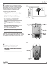
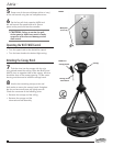
Atria
™
15
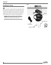
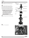
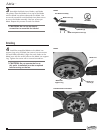
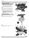
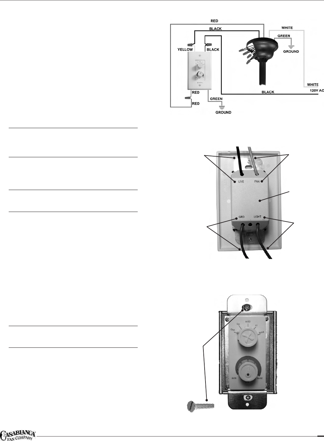
3 To attach the wires in the wall box to the W-81
wall control wires, match the wire colors as described
below, hold the bare ends of the wires side by side,
and fully insert the wires into the wire nut. Secure
by rotating the wire nut in a clockwise motion.
Connect wires in the following order:
GREEN GROUND conductor from the wall box to •
the GREEN wire from wall control (labeled GRD)
BLACK wire from fan in the wall box to •
YELLOW wire on wall control (labeled FAN)
RED wire from fan in the wall box to RED •
wire on the wall control (labeled LIGHT)
NOTE: BLUE D1 optional fan wire can be
connected to RED power wire in ceiling outlet
box.
BLACK wire from the source of power •
(HOT WIRE) wire in the wall box to BLACK
wire on wall control (labeled LIVE)
NOTE: If the colors of your wiring differ from
that described, consult an electrician.
Inspect each wire nut to ensure that no bare wire is visible.
Test the connection by gently pulling on the wires. The wire
nuts should stay firmly in place, covering the bare ends.
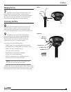
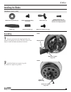
4 Fasten the W-81 wall control into the
wall box with the two switch box screws.
CAUTION: Ñ Be certain that the wires are
not pinched!
STEP 3
BLACK wire
(LIVE)
GREEN wire
(GRD)
RED wire
(LIGHT)
YELLOW wire
(FAN)
STEP 4
W-81 wall
control
(back view)
Switch box
screws (2)