


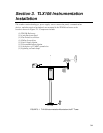

Section 3. TLX106 Instrumentation Installation
3-8
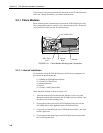
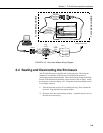
3. Connect the SC932C 9-pin port to the internal TLX106 Enclosure 9-pin
port with the blue ribbon cable provided.
4. Wire the Rad Modem to the TLX106 Enclosure with the 12 inch patch
cord. Match wire labels to wiring panel labels on both the TLX106
Enclosure and the Rad Modem (+XMT to +XMT, etc.). A small screw
driver in provided with the TLX106 Enclosure to access the Rad Modem
connections.
3.3.2.2 External Installation
The following short-haul kit components are used to make the external
connections:
At the TLX106 Enclosure:
(1) 20 foot 4-Wire Patch Cable
(2) 2 Direct Burial Splice Kits
(1) Length of User Supplied Wire (Supplier: Anixter, p/n F-02P22BPN,
Phone 847-677-2600)
At the PC:
(1) Rad Modem
(1) 5 foot 4-wire Patch Cable
(1) 10 foot 14 AWG Ground Wire
(1) Surge Protector and Case
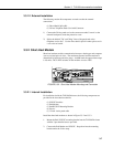
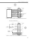
1) Connect the 20 foot patch cable to the connector marked "comm" on the
external back panel of the TLX106 Enclosure. Splice this cable to the
user supplied cable, using the direct burial splice kits.
2) Mount the surge protector to a flat surface near the PC's serial port.
Ground the center terminal to an earth (or building) ground using the 14
AWG wire.
3) Connect the 5 foot patch cord to the Rad Modem. Fasten the cable to the
strain relief tab with a cable tie. Connect the Rad to the PC's serial port
either directly (25 pin port) or through a 9 to 25 pin serial converter.
4) Route the user-supplied cable from the remote splice to the surge
protector. Connect it and the 5 foot patch cord to the surge protector.