


Section 3. TLX106 Instrumentation Installation
3-5
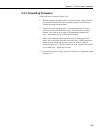
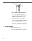
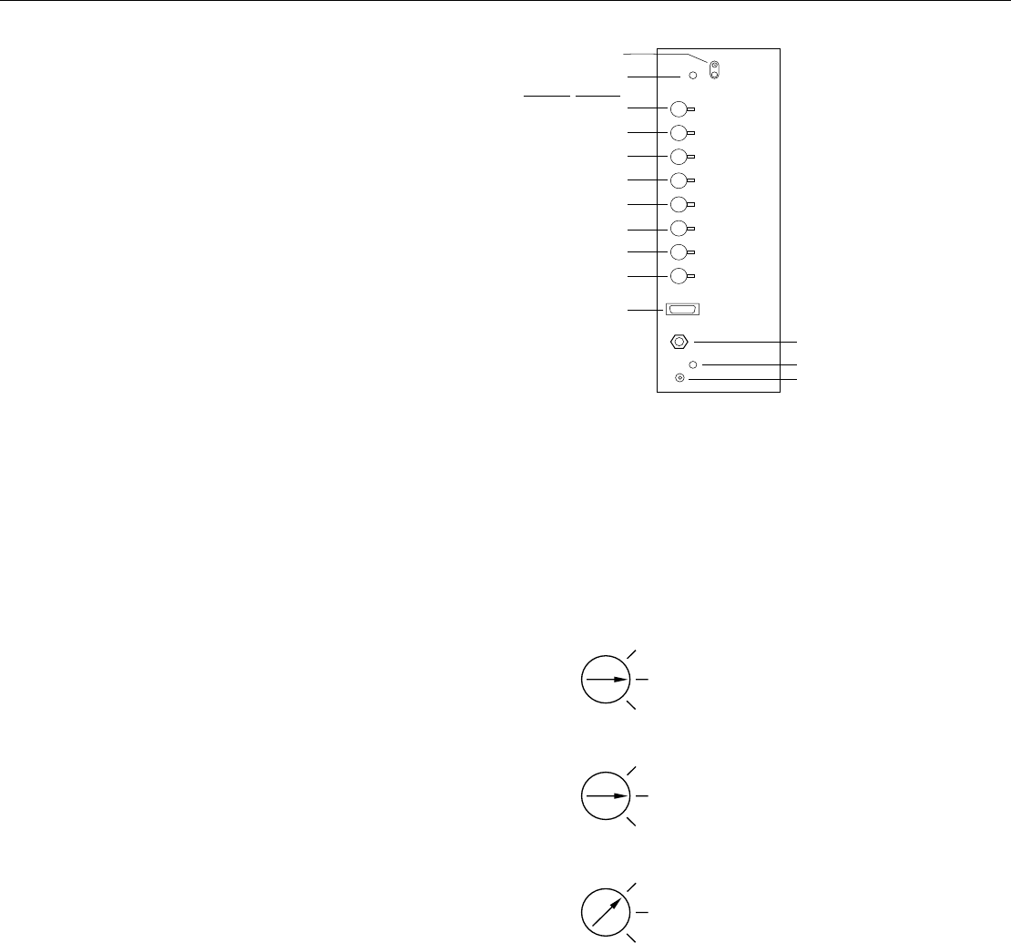
Earth
Ground
Stand off
Connector
#4
Sensors
TEMP
CS615
TEMP
RAIN
(PRECIP)
TEMP / RH
SOLAR
RADIATION
COMM
WS/WD
SDI 12
GYP BLOCK
#2
#6
#7
#5
#1
#3
#8
CS I/O
POWER CABLE PORT
STAND OFF
COAXIAL CONNECTION
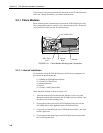
FIGURE 3.2-1. Position of Sensor Bulkhead Connectors
3) Replace the protective connector cover after sensors are connected and
power and communications cables are installed. Ensure that all cables
and connector caps are under the cover before tightening the screws.
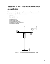
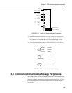
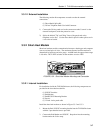
4) Configure sensor switch settings as shown in Figure 3.2-2 if necessary.
Open
604 Ohm
100 Ohm
(LI1200X)
(LI190SB)
(LI200S)
Open
1 K
Open
(CS500, HMP45C)
(CS500, HMP45C)
(HMP35C)
Open
SW 12V
5V
(HMP35C)
FIGURE 3.2-2. Default Sensor Switch Settings
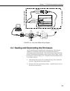
3.3 Communication and Data Storage Peripherals
One communications kit can be mounted to the TLX106 Enclosure back plate.
Communication kits ordered with the TLX106 Enclosure are pre-mounted and
pre-wired; no further connections inside the enclosure are necessary. Follow
the "External Installation" procedures outlined below to make the external
connections.