Section 3. TLX106 Instrumentation Installation
3-4
O
R
T
H
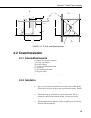
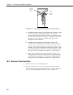
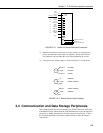
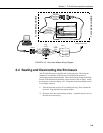
FIGURE 3.1-3. Mounting and Grounding the TLX106 Enclosure
c) Slide the enclosure to the top of the TLX106 tower. Position it on the
north side of the tower (northern hemisphere). The top of the
enclosure should be flush with the top of the tower, with the width of
the sensor arm extending above the tower. Tighten the clamps until
the enclosure is snug. Do not over-tighten since doing so may
damage the tower or enclosure.
d) Carefully mount the lightning rod and clamp to the top of the
TLX106 Tower. Clearance between the clamp and the enclosure is
minimal. Care should be taken not to scratch the enclosure or sensor
assembly. Strip 1 inch of insulation from the top end of the 12 AWG
green tower ground wire, curl the end and place the curled end under
the head of one of the lightning rod clamp bolts. Tighten the bolt.
e) Strip 1 inch of insulation from each end of the 9 inch piece of 12
AWG ground wire. Insert one end into the brass ground lug located
at the top back of the enclosure. Curl the other end and place under
the head of one of the lightning rod clamp bolts. Tighten the bolt.
3.2 Sensor Connection
1) Install the sensor set as described in Section 4.
2) Remove the protective connector cover from the back of the TLX106
Enclosure by removing the two phillips head screws. Sensors connect to
one of seven labeled bulkhead connectors as shown in Figure 3.2-1.
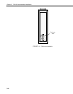
9-inch
Ground
Wire
Tower
Ground
Wire


