


4 5
ELECTRONIC FEATURES
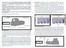
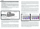
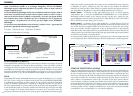
All electronic controls are push-button switches located at the rear of the unit housing as shown in
Figure 1. To ensure proper operation of the push button switches we recommend pressing firmly on
the center of the switch.
1. ON/Auto Battery Check
Depressing the Up Arrow push-button switch will turn the sight ON. The sight will
automatically perform a battery check every time it is turned on. If the batteries have less than
20% of life left, the sight will turn on with the reticle image blinking on and off for 5 seconds.
If the remaining battery life is more than 20%, the sight will turn on with a steady reticle pattern.
The battery condition can be checked any time by turning the sight off and back on.
2. OFF
To turn the sight off, depress both UP and DOWN arrows simultaneously. Verify by looking
through heads-up display window.
3. Brightness Adjustment
Push-button switches vary the brightness intensity of the holographic reticle pattern. Depressing
and releasing the push-button switches moves the brightness level UP or DOWN one (1) step
from the previous setting. Depressing and holding the up arrow or down arrow switch will
change brightness level up or down continuously in steps. There are twenty (20) brightness
settings providing a dynamic range of 20,000:1 from the lowest setting to the highest setting.
When the sight is turned ON, the brightness intensity level is automatically set to Level 12.
4. Auto Shutdown
The BUSHNELL HOLOsight is equipped with auto shutdown capability and will automatically
shut itself OFF 8 hours after the last push-button control is used.
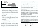
MOUNTING
The BUSHNELL HOLOsight is equipped with mounting hardware to attach to a standard 1" dovetail
or Weaver® style rail. To achieve the best results and accuracy, the BUSHNELL HOLOsight must be
mounted properly. The 1" dovetail rail needs to be as parallel as possible to the bore to achieve the best
accuracy. We strongly recommend you have the dovetail rail installed by a qualified gunsmith. Should
you decide to install the mount and sight yourself, please follow these steps:
1. Use a high-quality 1" steel dovetail rail mount designed to fit your particular firearm.
2. Carefully follow the instructions packed with the dovetail rail mount you have selected. Pay
careful attention to aligning the dovetail base parallel to the bore of the firearm.
3. The dovetail base should be mounted as low as possible.
4. Locate the post and dovetail clamp on the underside of the sight. Loosen the hex nut retainer
screw and the dovetail clamp with an Allen wrench (7/64).
5. Place the post within a groove on the top of the 1" dovetail base. Individual preference and the
specific firearm determines the optimal positioning to any specific groove on the dovetail base.
6. Make sure the post is inserted fully into the mount’s groove and push the sight as far forward as
possible. Tighten hex nut and retainer screw.
NOTE: Loosen screw just enough to mount and dis-mount the sight. Do not back screw out
completely to avoid losing the Weaver lock hardware.
BORE SIGHTING AND ZEROING
Bore sighting is a good preliminary procedure in achieving proper alignment of your sight to the
firearm. If the 1" dovetail rail is not mounted parallel to the barrel, major elevation adjustments may
be accomplished by shimming the dovetail base. It is important not to use the elevation adjustment
of the sight for major adjustments. Your sight’s internal elevation and windage adjustments should
be reserved for fine-tuning to achieve zero at the called for distance. Final zeroing of your firearm
and sight should be done with live ammunition and based on your expected shooting distance. If
you anticipate most of your shooting at short range, zero in at 50 yards. Groups of three shots will
be useful for averaging the point of impact.
WINDAGE AND ELEVATION ADJUSTMENTS
Your BUSHNELL HOLOsight features click mechanisms for elevation and windage adjustments.
The elevation and windage adjustment are located on the right-hand side of the sight (Figure 1). The
knob towards the front is your windage adjustment and the knob towards the rear is your elevation
adjustment (Figure 1). Both of these adjustment mechanisms are grooved with a slotted screw head
and require the use of a screwdriver, coin, or spent brass to turn.
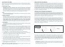
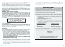
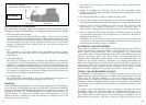
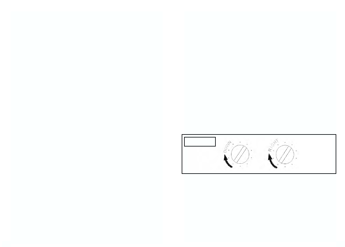
The elevation and windage adjustments are shown in Figure 3. For both elevation and windage, each
click will change the bullet’s point of impact 1/2 Minute of Angle (MOA), which translates to 1/4
inch at 50 yards, 1/2 inch at 100 yards. Also, one full rotation of either knob will change your point
of impact 10 MOA. This translates into 5 inches at 50 yards, 10 inches at 100 yards. To move the
point of impact UP, turn the adjustment screw counterclockwise; to move the point of impact
DOWN, turn the adjustment screw clockwise.
To move the point of impact RIGHT, turn the adjustment screw clockwise; to move the point of
impact LEFT, turn the adjustment screw counterclockwise. The elevation and windage adjustments
have been initially set at the factory near the midpoint of their adjustment ranges and should be close
to being at zero with a properly installed mounting rail. Please do not turn the adjustments before
mounting the sight on the firearm. Be sure to check that the mount and the sight remain secured
after the first shots are fired.
CAUTION-When encountering a sudden increase in resistance in these adjustments, the end of
the adjustment range has been reached. DO NOT TRY to turn the adjustments any farther or
serious damage may occur to the sight.
Elevation Windage
Figure 3