3-72
435/485/535
Section 3 - Operation
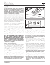
Hydraulic System Overview
Hydraulic System
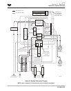
The tractor comes equipped with either a standard
manual hydraulic or the optional electro-hydraulic
(EHR) system. The system consists of a hydraulic
reservoir, a load-sensing variable-flow hydraulic
pump, an implement valve assembly with flow control
capability, quick couplers, a filter and oil coolers as
standard equipment.
A master control valve provides priority flow for
steering and excess flow to the implement valve.
A closed center steering motor receives priority flow
which feeds the steering cylinders.
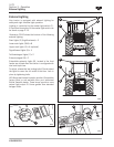
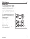
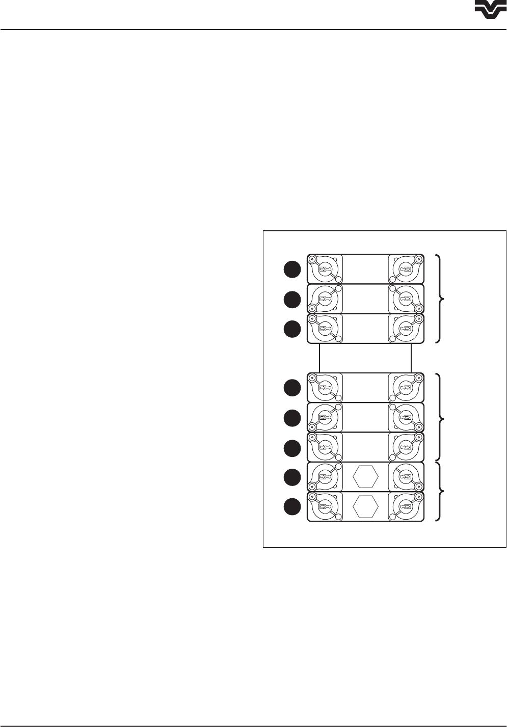
Hydraulic Quick Couplers
Tractors with manual hydraulics are equipped with
four or six remote couplers. Tractors with optional
electro-hydraulics (EHR) are equipped with four, six
or eight couplers.
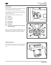
Each remote coupler is color coded with it’s
corresponding control lever.
From bottom to top:
1. Control lever 1 (Green) with load check
2. Control lever 2 (Blue) with load check
3. Control lever 3 (Brown)
4. Control lever 4 (Gray)
5. Control lever 5 (Black)
6. Control lever 6 (White)
7. Control lever 7 (Purple)
8. Control lever 8 (Lime)
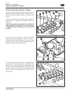
Load checks are installed in the “extend” port of the
lower two control valves 1 and 2.
F3-117
Pump 2
Pump 3
Pump 1
1
2
3
4
5
6
7
8


