


8
CAUTION: Incorrect cable
adjustment could cause the
wheels and tines to rotate
unexpectedly. Follow
adjustment procedures
carefully. Failure to do so could
result in personal injury or
property damage.
4. Check for correct spring⁄cable tension
as instructed in Section 5, Checking and
Adjusting Forward Clutch Belt Tension.
5. When tension is correct, tighten the two
jam nuts (B) securely.
STEP 5: CHECK TRANSMISSION GEAR
OIL LEVEL
The transmission was filled with gear oil at
the factory. However, be sure to check the
oil level at this time to make certain it is
correct.
IMPORTANT:
Do not operate the tiller if
the gear oil level is low. Doing so will result
in severe damage to the transmission
components.
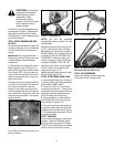
1. With the tiller on level ground, pull the
Depth Regulator Lever (R, Figure 2-13)
back and then slide it to the second notch
from the top. NOTE: If the lever does not
move, lift the tine hood flap and look for a
plastic tie securing the lever in place. Cut
and remove the tie.
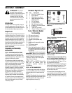
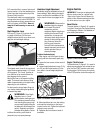
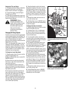
2. Remove the oil level check plug (M, Fig-
ure 2-10) on the left-side of the transmis-
sion. (Due to dried paint on the plug
threads, it may require some force to re-
move the plug the first time.) The gear oil
level is correct if oil starts to flow out of the
hole as the plug is removed. If so, securely
reinstall the plug.
3. If oil does not flow from the check hole,
add oil as follows:
NOTE: Do not use automatic
transmission fluid or motor oil in the
transmission.
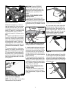
(a) Clean area around the fill hole (N, Fig-
ure 2-11) and unscrew gear oil fill plug.
(b) If adding only a few ounces of gear oil,
use API rated GL-4 or GL-5 gear oil having
a viscosity of SAE 140, SAE 85W-140 or
SAE 80W-90. If refilling an empty trans-
mission, use only GL-4 gear oil having a
viscosity of SAE 85W-140 or SAE 140.
(c) Using a clean funnel, slowly add gear
oil until it flows from the gear oil level
check hole (N, Figure 2-11).
(d) Reinstall and tighten securely the gear
oil fill plug (M, Figure 2-10).
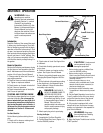
STEP 6: ATTACH WHEEL GEAR LEVER
1. Insert the Wheel Gear Lever (P, Figure 2-
12) up through the slot in the control panel
that is labeled “WHEEL GEAR.”
2. Insert two #10-32 x 1⁄2" round head
screws down through the “+” marks on the
control panel decal and securely attach the
wheel gear mounting bracket using two
#10 lock washers and #10-32 nuts.
3. Use a small board or rubber mallet to
tap the Wheel Gear Lever knob securely
onto the lever (R, Figure 2-13).
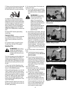
4. Secure the wheel gear cable and the re-
verse clutch control cable to the left-side
handlebar with two plastic ties (S, Figure
2-13) located about two feet apart. Snip off
any excess tie length.
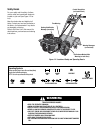
STEP 7: CHECK AIR
Use a tire pressure gauge to check the air
pressure in both tires. Deflate or inflate
both tires equally to between 15 PSI and
20 PSI. Be sure that both tires are inflated
equally or the unit will pull to one side.
STEP 8: CHECK HARDWARE
Inspect the hardware on the unit and tight-
en any loose screws, bolts and nuts.
Figure 2-10: Gear oil level check plug.
Figure 2-11: Adding gear oil.
Figure 2-13: Attach wheel gear cable and re-
verse clutch cable with cable ties (S).
Figure 2-12: Attach Wheel Gear Lever.
M
N
P
S
R