


10
3. To move the tiller in reverse, first stop all
forward motion. Lift up the handlebars un-
til the tines clear the ground and pull the
Reverse Clutch lever out.
The wheels will rotate in a reverse direction
as long as the lever is held in REVERSE. To
stop the wheels and tines, release the lever
and it will return to NEUTRAL. Never at-
tempt to till while moving in reverse di-
rection.
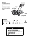
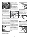
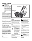
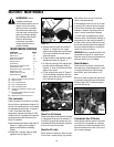
Depth Regulator Lever
This lever (E, Figure 3-2) controls the till-
ing depth of the tines. Pull the lever
straight back and slide it up or down to en-
gage the notched height settings.
The highest notch (lever all the way down)
raises the tines approximately 1-1⁄2 inches
off the ground. This “travel” position al-
lows the tiller to be moved without the
tines digging into the ground.
Moving the lever up increases the tilling
depth. The lowest notch allows a tilling
depth of approximately six to eight inches,
depending on soil conditions.
For best results, always begin tilling at a
very shallow depth setting and gradually
increase tilling depth.
WARNING: Place Depth
Regulator Lever in “travel”
position before starting engine.
This position prevents the tines
from touching the ground until
you are ready to begin tilling.Do
not attempt to till too deeply too
quickly. Gradually work down
to deeper tilling depths. Failure
to follow this warning could result in
personal injury or property damage.
Handlebar Height Adjustment
Handlebar height is adjustable to four dif-
ferent settings. When setting the height,
keep in mind that the handlebars will be
lower when the tines are engaged in the
soil.
WARNING: Whenever the
handlebar height is changed,
the Forward Clutch shift
mechanism must be
readjusted. Before adjusting or
checking the Forward Clutch
mechanism, shut engine off,
disconnect spark plug wire and
prevent it from touching spark
plug. Failure to follow this
warning could cause the
Forward Clutch mechanism to
operate improperly which could
result in personal injury or
property damage.
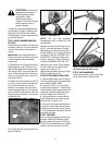
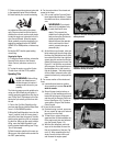
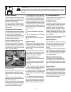
To Adjust Handlebar Height:
1. Stop engine, wait for all parts to stop
moving and then disconnect spark plug
wire.
2. Loosen the two screws at lower ends of
handlebar.
3. Loosen height adjustment screw (F, Fig-
ure 3-3) and pull keyed washer (G) free
from slots in curved height adjustment
bracket.
4. Move handlebars to a new slot setting
and insert the raised key on the keyed
washer into the slot. Tighten the height ad-
justment screw securely.
5. Retighten the two screws at ends of
handlebar.
Engine Controls
IMPORTANT: The engine is equipped with
either a choke control or a primer bulb.
Refer to the Engine Owner’s Manual (in-
cluded in tiller literature package) to iden-
tify which device is on your engine.
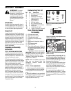
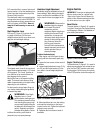
Recoil Starter
The recoil starter (H, Figure 3-4) is used to
“pull-start” the engine. See Engine Starting
and Stopping in Section 4 for detailed en-
gine starting instructions.
Engine Throttle Lever
The throttle lever (D, Figure 3-1) is used to
adjust engine speed as well as stop the en-
gine. Use the START position when start-
ing the engine. Pull the lever all way back
to the STOP position to shut the engine off.
Figure 3-2: Depth Regulator Lever.
Figure 3-4: Recoil starter handle.
Figure 3-3: Handlebar height adjustment.
E
G
F
H