


7
5. Move the handlebars up or down to
align the threaded hole in the cross-brace
with one of the four slots in the curved
height adjustment bracket. Place the keyed
washer (E, Figure 2-3) on the flange head
height adjustment screw (F) with the
raised keys (edges) of the washer facing
down.
6. Thread the height adjustment screw (F,
Figure 2-3) into the hole in the handlebar
cross-brace, making sure that the raised
keys on the washer fit into the slot on the
height adjustment bracket. Tighten the
height adjustment screw securely. Next,
securely tighten the two screws and nuts
in the ends of the handlebar (M, Figure 2-
3).
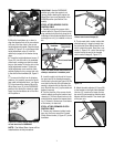
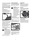
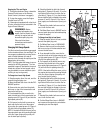
7. To remove the tiller from its shipping
platform, first carefully unwrap the wheel
gear cable (with attached lever - see Figure
2-5) from around the chassis. Move the
Wheel Gear Lever (G) to the DISENGAGE
position--this allows the wheels to rotate
freely. Use the handlebars to roll the tiller
off the platform.
NOTE: The Wheel Gear Lever will be
installed later in this procedure.
IMPORTANT:
Use the DISENGAGE
position only when the engine is not
running. Before starting the engine, the
Wheel Gear Lever must be placed in the
ENGAGE position (see Section 3 for
details).
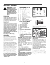
STEP 3: ATTACH REVERSE CLUTCH
CONTROL CABLE
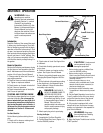
1. Carefully unwrap the reverse clutch
control cable (H, Figure 2-6) from its ship-
ping position and route it up along the in-
side edge of the left side handlebar. A knob
and large hex nut (I) is installed on the ca-
ble.
2. Insert the cable into the slot in the con-
trol panel and fit the threaded assembly
into the hole in the slot (see Figure 2-6). Be
sure that the flat side of the threaded as-
sembly is aligned with the flat side of the
hole. Slide the hex nut (I) up the cable and
tighten it securely.
3. Test the function of the reverse clutch
control cable by pulling the knob out and
releasing it. The knob should return to its
neutral position against the tapered bush-
ing. If it doesn’t, contact your local dealer
or the factory for technical.
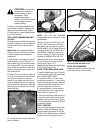
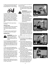
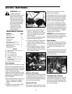
STEP 4: ATTACH FORWARD CLUTCH
CONTROL CABLE
1. Remove any fasteners (rubber bands,
tape, etc.) that may secure the Forward
Clutch Control levers (J, Figure 2-7) to the
handlebar.
2. The forward clutch control cable (with
attached spring) is hanging loosely near
the right-side wheel. Being careful not to
kink or stretch the cable, insert the z-con-
nector (L, Figure 2-8 – end of the spring)
into the hole at the end of the forward
clutch control linkage (K, Figure 2-7).
3. Attach the cable adjuster (A, Figure 2-9)
to the bracket on the right-side handlebar.
Use two 1⁄2" wrenches to loosen the two
jam nuts (B) just enough to slide the cable
adjuster onto the bracket. Then hand tight-
en the jam nuts.
Figure 2-6: Attach reverse clutch control as-
sembly to slotted hole in handlebar panel.
Figure 2-5: Carefully unwrap Wheel Gear Le-
ver and move lever to DISENGAGE.
Figure 2-7: Forward Clutch Control levers (J).
Forward clutch control linkage (K).
Figure 2-8
Figure 2-9
C
N
P
O
Figure 2-4: Attach handlebars.
G
Left Side
Handlebar
Reverse Clutch
Control Knob
Slot in Control Panel
I
H
K
J
L
B
A