


31
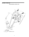
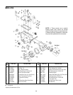
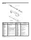
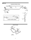
ENGINE
TINE
SHAFT
DENOTES CUTTING EDGE
OF TINE
MODEL 675B
3
7
1
5
3
4A
1
3
2
7
1
1
1
1
1
7
5
3
1
1
4
2
3
3
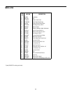
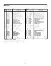
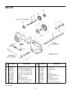
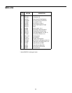
REF
NO.
PART NO. DESCRIPTION
1 1100068 Hex Hd. Screw, 3/8-16 x 3/4*
2 1985101 Tine – right-hand
3 1110108 Hex Lock Nut, 3/8-161
4 1916693 Tine Holder, left-side
4A 1916694 Tine Holder, right-side
5 710-3096 Hex Hd. Screw, 3/8-16 x 2, Grade 8
6 GW-9338 Hitch Pin
7 1985100 Tine – left-hand
8 GW-9380 Clevis Pin,.312 x 1-3/4 long
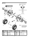
9 634-04033 Wheel & Tire Assy., left-side
10 634-04032 Wheel & Tire Assy., right-side
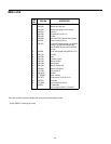
REF
NO.
PART NO. DESCRIPTION
Mount Tines So The Cutting Edge At The
Top Of Each Tine Faces The Operator
IMPORTANT: LEFT and RIGHT sides of tiller
are determined by standing in
the operator position (BEHIND
THE HOOD) and facing the di-
rection of forward travel.
LEFT-HAND TINE RIGHT-HAND TINE
(TOP)
(BOTTOM)
8
6
6
8
9
10