


20
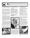
NOTE: While pushing inward on the
forward idler arm, be sure that the
forward drive belt is moved off to the
right side of the tiller. This creates
more room to install the clevis pin
when the forward idler arm is pushed
inward.
IMPORTANT:
When the clevis pin is
installed in the inner hole of the forward
adjustable link, the number of additional
belt tension adjustments are limited. If,
with future tension adjustments, you find
that you cannot screw the forward clutch
rod any farther into the rectangular nut on
the forward clutch bracket, it means that
the forward drive belt must be replaced.
Before doing so, the clevis pin must be
returned to the OUTSIDE hole in the
forward adjustable link.
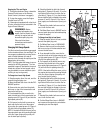
8. Replace the forward drive belt in the
High speed groove (groove closest to en-
gine) or the Low speed groove (rearmost)
groove of the engine drive pulley and in the
matching groove of the transmission pul-
ley. Be sure the belt is to the inside of the
wire formed belt guide (I, Figure 5-12) and
to the inside of the forward drive idler pul-
ley (J).
9. Reinstall the belt cover and secure it
with the two nuts.
10. Readjust the forward drive belt tension
by following the instructions in Section 3:
Handlebar Height Adjustment.
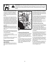
To Check and Adjust Tension on the Re-
verse Drive Belt:
1. Remove the belt cover after first shut-
ting off the engine, disconnecting the
spark plug wire, and allowing the engine
and muffler to cool down.
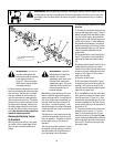
2. Stand at the front of the tiller and use
your left hand to push the reverse idler
arm (K, Figure 5-13) inward as far as pos-
sible (the reverse idler pulley [L] is at-
tached to the reverse idler arm).
Hold the idler arm in this position and look
at the position of the belt tension guide
mark (M, Figure 5-14) that is stamped into
the face of the reverse adjustable link (N,
Figure 5-14).
• The tension is correct if the guide mark
(M, Figure5-14) is anywhere to the left of
the guide pin (O), as viewed from the
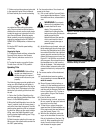
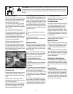
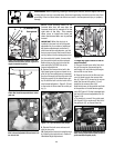
Figure 5-10: One or two threads on Forward
Clutch Rod should be exposed above rectan-
gular nut.
Figure 5-9: Disconnect Forward Clutch Rod
and move forward drive belt out of groove in
engine forward drive pulley.
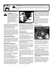
Figure 5-11: Remove clevis pin from outer
hole in forward adjustable link and move to in-
ner hole in link.
Figure 5-12: Top view of belts and pulleys.
Figure 5-13
Figure 5-14: While pushing reverse idler arm in-
ward, stand at engine end and check position of
guide mark (M) and guide pin (O).
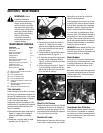
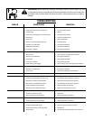
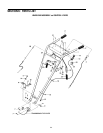
WARNING: Before inspecting, cleaning or servicing the machine, shut off engine, wait for all
moving parts to come to a complete stop, disconnect spark plug wire and move wire away from
spark plug. Failure to follow these instructions can result in serious personal injury or property
damage.
A
B
C
(E) Remove belt
from groove
D
Threads
I
V
J
G
H
F
P
L
K
R
O
N
M