


18
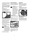
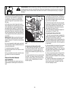
Carburetor / Governor Adjustment
WARNING: Operators
shall not tamper with the engine
governor settings; the governor
controls the maximum safe
operating speed to protect the
engine and all moving parts
from damage caused by
overspeed. Authorized service
shall be sought if a problem
exists.
The carburetor was adjusted at the factory
for best operating speed. Refer to the sep-
arate Engine Owner’s Manual for any ad-
justment information or see your
authorized engine service dealer.
The governor controls the maximum safe
operating speed and protects the engine
and all moving parts from damage caused
by overspeeding. Do not tamper with the
engine governor settings. Seek authorized
service if a problem exists.
Throttle Control Adjustment
If the engine does not respond to various
throttle lever settings, refer to the separate
Engine Owner’s Manual for service infor-
mation or contact your local authorized en-
gine service dealer.
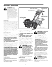
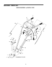
Wheel Gear Cable Adjustment
When the Wheel Gear Lever is in DISEN-
GAGE, the wheels will roll freely (free-
wheel). The wheels should not roll freely
when the lever is in ENGAGE. If the wheels
roll freely when the Wheel Gear Lever is in
ENGAGE, the wheel gear cable needs to be
adjusted as described below.
1. With the engine shut off and the spark
plug wire disconnected, put the Wheel
Gear Lever in ENGAGE.
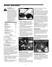
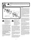
2. Loosen the top adjustment nut
the wheel gear cable bracket located on the
left side rear of the transmission.
3. Push wheel gear cable (B) down and roll
tiller slightly forward or backward until ec-
centric lever (C) engages (locks) wheels.
Hold cable in that position and tighten top
(A) and bottom (D) adjustment nuts.
4. Move Wheel Gear Lever to ENGAGE and
DISENGAGE several times to check adjust-
ment. The wheels should not roll when the
lever is in ENGAGE, but they should roll
when the lever is in DISENGAGE. Readjust
the cable as required.
Off Season Storage
When the tiller won’t be used for extended
periods, prepare it for storage as follows:
1. Clean the tiller and engine.
2. Do routine tiller lubrication (see Tiller
Lubrication) and check for loose parts and
hardware (see Check Hardware).
3. Protect the engine by performing the
engine storage instructions in the separate
Engine Owner’s Manual.
NOTE: Be sure to protect the fuel lines, car-
buretor and fuel tank from gum deposits
by removing fuel or by treating fuel with a
fuel stabilizer (follow engine manufactur-
er’s recommendations).
4. Store unit in a clean, dry area.
5. Never store the tiller with fuel in the fuel
tank in an enclosed area where gas fumes
could reach an open flame or spark, or
where ignition sources are present (space
heaters, hot water heaters, furnaces, etc.).
Tines
The tines will wear with use and should be
inspected at the beginning of each tilling
season and after every 30 operating hours.
Tines can be replaced individually or as a
complete set. Never inspect or service the
tines unless the engine is stopped and the
spark plug wire is disconnected.
NOTE: The tiller hood must be
removed to take off either a single tine
holder or individual tines. The hood is
secured to the transmission housing
with two rear bolts and two front bolts.
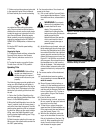
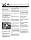
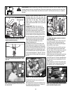
Tine Inspection
With use, the tines (Figure 5-6) will be-
come shorter, narrower and pointed. Badly
worn tines will result in a loss of tilling
depth and reduced effectiveness when
chopping up and turning under organic
matter.
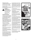
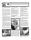
Removing and Installing
1. Use a 9/16" socket, 6" extension, a
ratchet, and a 9/16" box wrench to loosen
the nut (A, Figure 5-7) and bolt (B) that se-
cure the tine holder to the tine shaft.
2. Use a rubber mallet to tap the tine hold-
er loose.
3. Slide the tine assembly off the tine shaft.
4. Repeat Steps 1-through-3 above to re-
move the other tine assembly.
5. Installing the tine assembly is simply
the reverse of its removal. Be sure the cut-
ting edges face so they will enter the soil
first when the tiller is moving forward– this
means the cutting edges face toward the
operator position.
First be sure to remove any rust, uneven
spots or burrs from the tine shaft, using
fine sandpaper. Then grease the tine shaft
before reinstalling the tine assemblies.
Tighten the hardware very securely.
Figure 5-5: Wheel gear cable assembly.
Figure 5-6: Four tine gangs: two per side.
WARNING: Before inspecting, cleaning or servicing the machine, shut off engine, wait for all
moving parts to come to a complete stop, disconnect spark plug wire and move wire away from
spark plug. Failure to follow these instructions can result in serious personal injury or property
damage.
B
A
C
D