


21
front of the unit (not the operator’s posi-
tion). If the belt tension is correct, reinstall
the belt cover and secure it with the two
nuts.
• If the guide mark is aligned with the
guide pin, or moves to the right side of the
guide pin, then the belt is too loose and the
tension must be readjusted as described
next.
3. The reverse idler pulley (L, Figure 5-13)
regulates the tension that is applied to the
reverse drive belt (P). The following ad-
justment will allow the reverse idler pulley
to apply more tension to a loose belt.
4. Remove the belt cover.
5. Slip the reverse belt (P, Figure 5-13) off
the engine-driven reverse (upper) pulley.
6. On the right side of the unit (as viewed
from operator’s position), remove the hair-
pin cotter from the clevis pin (R, Figure 5-
13) that connects the reverse idler arm (K)
to the reverse adjustable link. Push inward
on the reverse idler arm (K) and remove
the clevis pin (R).
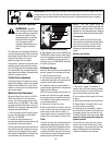
7. There are two holes in the reverse ad-
justable link (S, Figure 5-15). Push inward
on the reverse idler arm (K) and install the
clevis pin (R) through the inner hole in the
reverse adjustable link (S) and out through
the single hole in the reverse idler arm (K).
Secure the clevis pin with the hairpin cot-
ter.
8. Reinstall the reverse belt (P, Figure 5-13)
on the reverse (upper) pulley, making sure
the belt is located to the inside of the re-
verse idler pulley (L, Figure 5-13).
9. Reinstall the belt cover and secure it
with the two nuts.
IMPORTANT:
If, in future tests for
reverse belt tension, the guide mark
should again align with or move to the
right side of the guide pin, it means that
the reverse belt is worn beyond
adjustment. Before installing a new belt,
you must return the clevis pin to the
OUTSIDE hole in the reverse adjustable
link.
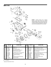
Forward Drive Belt Removal
and Installation
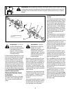
This model has two forward speeds (High
and Low) and one reverse speed. The for-
ward engine pulley (D, Figure 5-16) has
two grooves for the two forward speeds.
The reverse engine pulley (A, Figure 5-16)
has one groove for the one reverse speed.
The transmission pulley (C, Figure 5-16)
has three grooves. The groove closest to
the engine is for the reverse belt. The mid-
dle groove is for the High speed forward
belt range; the rearmost groove is for the
Low speed forward belt range.
A. Removing the Forward Drive Belt:
1. Stop the engine, allow it to cool and dis-
connect the spark plug wire before work-
ing near the belts.
2. Remove the reverse drive belt
following the Removing the Reverse Drive
Belt instructions in this section.
3. Move the forward drive belt (B, Figure
5-16) completely off the engine forward
drive pulley (D).
4. Slip the forward drive belt completely
off the transmission drive pulley (C, Figure
5-16) by moving it to the front of the pul-
ley.
5. Pull the forward drive belt up and off the
pulleys by feeding the bottom half of the
belt in between the engine and transmis-
sion pulleys.
B. Installing the Forward Drive Belt:
1. The reverse drive belt must be removed
before installing the forward drive belt.
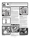
2. Slip the forward drive belt down between
the rear of the engine forward drive pulley
(D, Figure 5-16) and feed the bottom half in
between the engine and transmission pul-
leys (see Figure 5-17). Be sure that the belt
is to the inside of the forward idler pulley
and forward belt guide (see J and I, Figure
5-12).
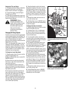
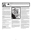
Figure 5-17: Install forward drive belt over
rear of engine forward pulley and bring lower
half of belt down and in front of transmission
pulley.
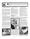
Figure 5-15: Installing clevis pin in inside hole
of reverse adjustable link.
Figure 5-16: Belt drive system.
WARNING: Before inspecting, cleaning or servicing the machine, shut off engine, wait for all
moving parts to come to a complete stop, disconnect spark plug wire and move wire away from
spark plug. Failure to follow these instructions can result in serious personal injury or property
damage.
S
R
K
DB
A
C
FRONT