


19
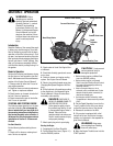
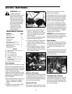
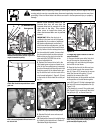
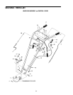
WARNING: This is a CRT
(counter-rotating tine) tiller
and its tines must be mounted
in the direction shown in
Figure 5-7. Failure to comply
could result in personal injury
or property damage.
2. When installing individual tines, install
them in the reverse order from which they
were removed. The two sets of inboard
tines are installed so one tine faces to-
ward the transmission housing and the
other tine faces away from it. The single
outboard tine on each side faces toward
the transmission housing. Also be sure
the cutting edges face so they will enter
the soil first when the tiller is moving for-
ward–this means the cutting edges face
toward the operator position.
Checking And Adjusting Tension
On Drive Belts
While checking belt tension, also check
for cracks, cuts or frayed edges. A belt
that is in poor condition should be re-
placed.
WARNING: Follow the
belt adjustment instructions
carefully. An incorrect
adjustment could result in the
Forward Clutch mechanism
engaging too soon. This could
cause loss of tiller control and
result in personal injury or
property damage.
Maintaining correct tension on the drive
belts is important to good tilling perfor-
mance and long belt life. A loose belt will
slip on the engine and transmission pul-
leys and cause the tines and wheels to
slow down – or stop completely – even
though the engine is running at full speed.
A loose belt will also result in premature
wear to the belt.
The tension on a new forward drive belt
should be checked after the first two (2)
hours of operation. Thereafter, check the
tension after every ten (10) hours of
operation.
The reverse drive belt, because it is used
infrequently, will not require an initial ten-
sion adjustment until a significant num-
ber of operating hours has passed.
To Check and Adjust Tension on the Forward
Drive Belt:
1. Checking for correct belt tension is the
same as that described in item 5, Step 4:
Attach Forward Clutch Rod. Before check-
ing, shut off the engine, disconnect the
spark plug wire, and allow the engine and
muffler to cool down. If, after following
the adjustment procedures, you cannot
get the correct gap on the forward clutch
rod adjustment bracket, you will need to
make a secondary adjustment as de-
scribed next.
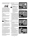
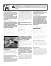
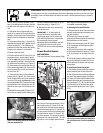
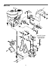
2. Disconnect the Forward Clutch Rod (A,
Figure 5-9) from the swivel plate (B) by
removing the innermost hairpin cotter
(C).
3. Unthread the Forward Clutch Rod (in a
counterclockwise direction as viewed
from the front of the unit) until one or two
threads on the rod extend above the rect-
angular nut (D, Figure 5-10) on the for-
ward clutch bracket.
4. Remove the belt cover.
5. Slip the forward drive belt (E, Figure
he engine-driven forward drive pulley by
pushing it off (away from engine) with
your left hand while pulling engine starter
rope with your right hand.
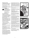
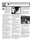
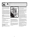
6. On the left side of the unit (from oper-
ator’s position) remove the hairpin cotter
from the clevis pin (F, Figure 5-11) that
connects the forward idler arm (G) to the
forward adjustable link (H). Push inward
on the forward idler arm (G) and remove
the clevis pin (F).
7. There are two holes in the forward ad-
justable link (H, Figure 5-11). Push in-
ward on the forward idler arm (G) and
install the clevis pin (F) through the inner
hole in the forward adjustable link (H) and
out through the single hole in the forward
idler arm (G). Secure the clevis pin with
the hairpin cotter.
Figure 5-7: Complete tine assemblies— holders, tines and hardware.
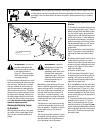
WARNING: Before inspecting, cleaning or servicing the machine, shut off engine, wait for all
moving parts to come to a complete stop, disconnect spark plug wire and move wire away from
spark plug. Failure to follow these instructions can result in serious personal injury or property
damage.
ENGINE
TINE
SHAFT
DENOTES CUTTING EDGE
OF TINE
C
D
A
B