


GB - 9
10. Replace the gear cover removed in step 4.
IMPORTANT: Rotate the discharge chute to the left
when tightening the pedestal hardware to ensure
clearance between the discharge chute and the belt
cover.
11. Tighten pedestal hardware to 15 – 31 lbf-ft (20 –
42 N•m).
12. Make sure the discharge chute rotates left and
right when you push the discharge chute control
lever left and right.
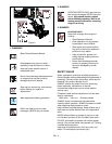
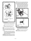
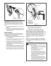
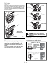
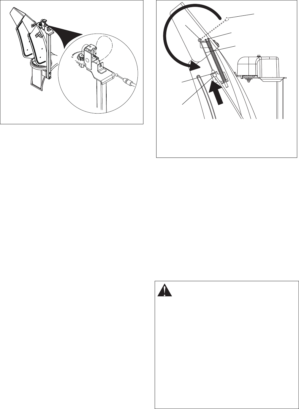
Deflector Remote
Connect the cable end to the cable anchor on the
discharge deflector before clipping the cable to the
cable bracket on the discharge chute.
1. Route deflector remote cable along the left side of
the chute pedestal.
2. Insert the barrel on the cable end into the bracket
on left side of chute deflector (Figure 9).
3. Hold seal out of the way while routing the cable
through the bracket on the left side of the
discharge chute, and then push the cable fitting
into the bracket.
4. Push the seal securely over the end of the cable
fitting to prevent water from entering the cable.
5. Check deflector travel. Adjust nut on cable end
under handlebar to obtain full travel, if necessary.
Connect Battery (926023, 500, 501)
1. Remove wing nuts from battery cover.
2. Install wire lead to battery terminal.
3. Install battery cover and tighten wing nuts.
Check Function of Dual Handle Interlock
Without the engine running, press down (engage) both
clutch levers. Release attachment clutch lever.
Attachment clutch should remain engaged until traction
clutch lever is released, then both clutches must
disengage. If they do not, contact your Dealer for
repairs.
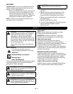
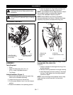
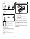
Check Tire Pressure (926016, 017, 500, 501)
Check tire pressure and adjust to the pressure listed on
tire sidewall.
Figure 8
OS7271
CAUTION: Avoid injury! Explosive separation
of tire and rim parts is possible when they are
serviced incorrectly:
• Do not attempt to mount a tire without
the proper equipment and experience to
perform the job.
• Do not inflate the tires above the
recommended pressure.
• Do not weld or heat a wheel and tire
assembly. Heat can cause an increase
in air pressure resulting in an explosion.
Welding can structurally weaken or
deform the wheel.
• Do not stand in front or over the tire
assembly when inflating. Use a clip-on
chuck and extension hose long enough
to allow you to stand to one side.
Figure 9
1.Cable Anchor
2.Cable End
3.Deflector Cable
4.Cable Fitting
5.Cable Bracket
1
2
3
5
4
3
OS7070