


GB - 8
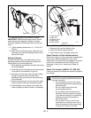
4. Remove the cover from the gear assembly on the
discharge chute.
5. Release the lock teeth on the gear assembly with
your finger and rotate the discharge chute 90
°
left.
6. Remove and save the hairpin from the control
assembly underneath the control panel.
NOTE: Do not remove the pin installed on the chute
rod.
NOTE: To ensure the discharge chute follows its full
range of travel, make sure the control lever is pushed
all the way to the left before installing and pinning the
chute rod.
7. Align the holes on the end of the chute rod with
the mark on the gear assembly and slide the end
without a pin through the gear assembly, through
the hook on the chute lock cable and into the hex
hole in the control assembly.
IMPORTANT: The hook will prevent the control cable
from contacting the engine or muffler guard. If the hook
gets damaged, loosely tie the cable to the control rod.
NOTE: After the chute rod has been inserted through
the hex hole in the control assembly, placing the unit in
the service position (see Service Position on page 19)
will ease alignment and installation of the hair pin.
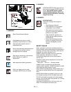
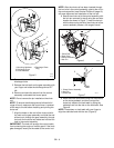
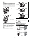
8. Secure the chute rod to the control assembly with
the hair pin removed in step 6 using the end hole
location as shown in Figure 7. Insert the hair pin
with the loop end to the left of the chute rod so the
control assembly follows a full range of travel.
9. Insert the chute lock cable fitting into the bracket
on the chute pedestal, and then connect the
chute lock cable to the lock teeth by fitting the
cable ball end into the slot on the lock teeth. See
Figure 8.
NOTE: Press down on lock teeth with your finger to
align the cable ball end with the slot (Figure 8).
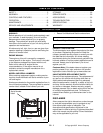
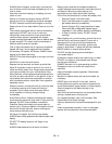
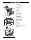
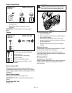
Figure 5
1.Mounting Hardware
2.Discharge Chute
3.Chute Pedestal
4.Discharge Chute
Ring
1
1
3
2
OS7040
OS7045
4
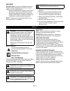
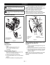
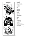
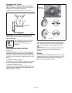
Figure 6
1.Chute Rod
2.Gear Cover
3.Control Assembly
4.Hair Pin
1
2
3
4
OS7060
Figure 7
1. Chute Control Assembly
2. Hair Pin
3. Chute Rod
1
2
3
OS7157