


GB - 29
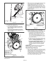
4. Install new traction drive belt onto attachment
pulley and engine sheaves.
5. Pull the drive plate assembly toward the friction
disc and tighten the stop bolt.
NOTE: Make sure the drive plate assembly return
spring remains connected to the frame.
6. Replace attachment drive belts (Attachment Drive
Belts Replacement on page 27.
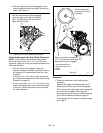
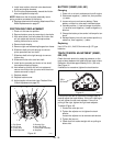
FRICTION DISC REPLACEMENT
1. Place unit into service position.
2. Remove bottom cover by removing six hex bolts.
3. With axle locked, hold one wheel so friction disc
will not rotate and remove three cap screws
holding friction disc to carrier.
4. Remove both wheels.
5. Remove right and left bearing flanges from frame.
6. Slide hex shaft to the left enough to remove
pinion sprocket from hex shaft.
7. Slide hex shaft to the right enough to remove
friction disc.
8. Slide new friction disc onto hex shaft.
9. Install pinion sprocket and chain on hex shaft,
then replace bearing flanges.
10. Hold wheel so friction disc will not rotate and
secure new friction disc to carrier with three hex
screws removed in step 2.
11. Replace wheels.
12. Replace bottom cover.
13. Adjust traction drive clutch (see Traction Drive
Clutch Adjustment on page 27).
BATTERY (926023, 500, 501)
Charging
1. Place unit on a level surface and shut off engine.
2. Disconnect negative (–) cable first, then positive
(+) cable.
3. Loosen wing nut and remove battery. Place
battery on bench or other well-ventilated place.
4. Connect positive (+) lead of charger to positive
(+) terminal, and negative (–) lead to negative (–)
terminal.
5. Charge the battery at two and a half amps for ten
hours.
6. Reinstall battery into unit and connect positive (+)
cable first, then negative (–) cable.
Replacing
Use U1R or U1L; 240 CCA minimum @ 0°F type
batteries.
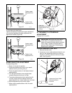
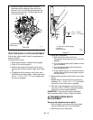
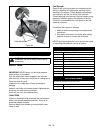
TRACK TENSION ADJUSTMENT (926021,
022, 023)
Check the track tension by applying pressure on the
track midway between the upper and rear track rollers.
Deflection should be approximately 3/8 in. (9.6 mm).
See Figure 41.
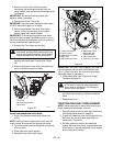
If deflection is excessive, tighten the track tension.
If unit pulls to the left or right when a straight path is
desired adjust the track tension. If the unit is pulling to
the left, tighten the left track adjuster. If the unit is
pulling to the right, tighten the right track adjuster.
To adjust (Figure 42):
1. Loosen the outer jam nut.
2. Tighten the adjuster nut to tighten the track
tension.
Loosen the adjuster nut to reduce track tension.
3. Tighten the jam nut.
4. Check that unit tracks straight with no pulling to
either side.
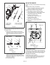
Figure 40
OS7225
1. Cap Screw
2. Hex Screw
3.Friction Disc
4. Pinion Sprocket
5. Bearing Cap
6.Idler Hex Shaft
7.Drive Plate Assembly
8.Stop Bolt
1
2
3
1
5
6
1
1
8
7
4
Figure 41
3/8 in.
(9.6 mm)
OS7226