


GB - 28
3. Remove hair pin under the control panel
connecting the discharge chute rod from the
chute rotation lever and slide the discharge chute
rod forward.
IMPORTANT: Disconnect chute lock cable and
deflector cable, if equipped.
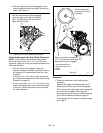
4. Remove belt finger (Figure 39).
IMPORTANT: Use care when rotating the belt fingers.
DO NOT bend belt fingers out of shape.
5. Remove attachment drive belts from engine
sheave (it may be necessary to turn engine
sheave using recoil starter handle).
IMPORTANT: To avoid bending bottom cover when
tipping unit apart, support handlebars firmly or tip unit
up on housing and remove bottom cover by removing
six cap screws before separating unit.
6. Support Sno-Thro frame and housing.
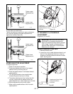
7. Remove hex bolts securing housing to frame. Tip
housing and frame apart on pivot pins (Figure
38).
8. Remove attachment drive belts from attachment
pulley (hold brake away from belts).
Install new attachment drive belts:
1. Place new attachment belts onto attachment
pulley.
NOTE: Holding down the attachment clutch lever will
make it easier to reconnect the housing and frame.
2. Tip housing and frame back together and secure
with hex bolts.
3. Place belts onto engine sheave.
4. Reposition and secure belt fingers.
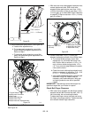
IMPORTANT: With clutch lever engaged, belt finger on
the side opposite the belt idler should be less than
1/8 in. (3 mm) from belts, but not touching the belts.
Adjust belt finger as necessary.
5. Check adjustment. See Check Belt Finger
Clearance on page 26
6. Reconnect chute crank and secure with spring
clip. Reconnect chute lock cable and deflector
cable.
7. Replace belt cover.
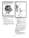
TRACTION DRIVE BELT REPLACEMENT
NOTE: Replacement will be easier with housing and
frame tipped apart and bottom cover off.
1. Remove attachment drive belts (see Attachment
Drive Belts Replacement on page 27).
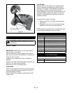
2. To gain belt clearance, back out the stop bolt from
the frame until the drive plate assembly can
swing past it (Figure 40).
3. Pull idler away from traction drive belt and
remove belt from idler pulley, engine sheave and
driven pulley (it may be necessary to turn engine
pulley using recoil handle).
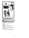
CAUTION: Always support Sno-Thro frame
and blower housing when loosening the cap
screws holding them together. Never loosen
cap screws while unit is in service position.
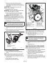
Figure 38
1.Pivot Pin
2.Housing Cap Screws
3.Belt Cover
2
3
1
OS7215
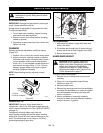
WARNING: AUGER / IMPELLER MUST
STOP within 5 seconds when attachment
clutch lever is released or unit damage or
serious injury may result.
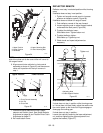
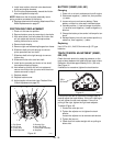
Figure 39
1.Traction Drive Belt
2.Engine Sheave
3.Attachment Drive Belts
4.Belt Finger
5.Attachment Belts Idler
6.Attachment Pulley
7.Attachment Idler
Adjustment Nut
8.Traction Belt Idler
9.Traction Drive Pulley
OS7221
1
2
3
4
5
8
9
6
7