


11 - 44
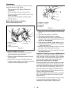
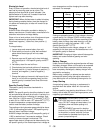
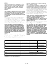
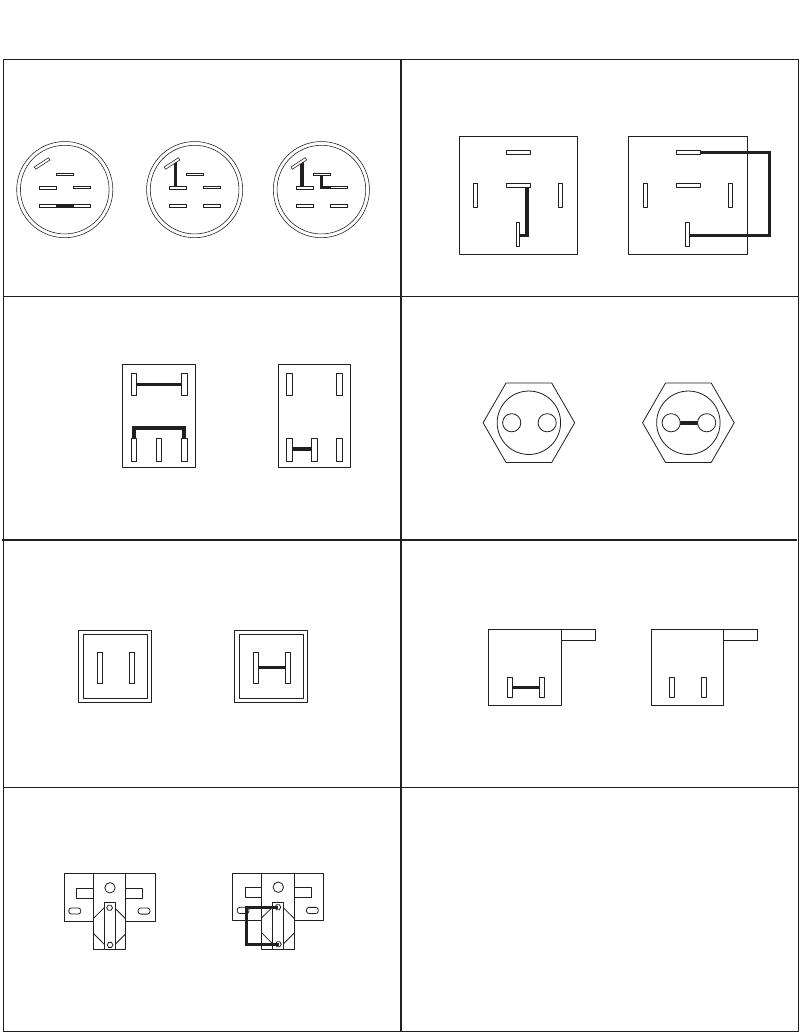
11.12 RELAYS AND SWITCHES
The diagrams below show the various states of connection for electrical components.
The solid lines on switches show continuity.
NOTE: All switches are viewed from the rear.
Key Switch
(03602300)
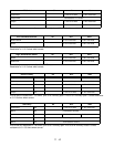
PTO Switch
(01545600)
Seat Switch
(03654200)
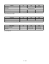
Brake Switch
(03657100)
Neutral Switch
(01526100)
1
2
ENGAGED
(button up)
1
2
DISENGAGED
(button down)
Relay
(03042800)
OFF
M
G
S2
B
S1
A
RUN
M
G
S2
B
S1
A
START
M
G
S2
B
S1
A
39
471
DISENGAGED
(down position)
39
471
ENGAGED
(up position)
1
OPERATOR
OFF SEAT
2
1
OPERATOR
ON SEAT
2
1
2
STEERING LEVER
OUT POSITION
(button down)
1
2
STEERING LEVER
IN POSITION
(button up)
87
87A
86 85
30
NOT ENERGIZED
87
87A
86 85
30
ENERGIZED
Solenoid
(03057700)
NOT ENERGIZED ENERGIZED
PE0520