


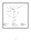

7 - 27
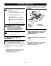
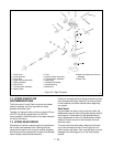
1. Install the displacement control shaft.
2. Install the pump input shaft assembly and retaining
ring into the housing.
3. Install the pump shaft lip seal.
4. Reposition the upper housing and install the cradle
bearings.
5. Install the slot guide block onto the displacement
control shaft.
6. Install the swashplate assembly into the housing.
The slot on the swashplate must engage the slot
guide block on the displacement control shaft. Use
a tool such as a screwdriver to hold the guide block
in position while installing the swashplate.
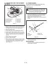
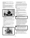
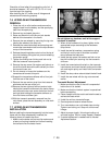
7. Install the thrust washer and pump block spring
onto the pump shaft.
NOTE:
To simplify the installation of the pump block,
wrap a rubber band snugly around the pistons. This is
intended to hold the pistons in their bores as the block
kit is handled during installation.
8. With the swashplate in the neutral (0 angle),
lubricate the running surfaces and install the block
kit onto the pump input shaft. Make sure the
splines engage properly.
9. Install the aligning pins and the bypass actuator
into the housing.
10.Install the bypass plate (small end first) into the
center section.
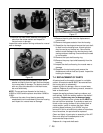
11.Lubricate the running faces and install the motor
block kit onto the motor shaft.
12.Position the washers and seal and install the
center section assembly onto the aligning pins and
pump input shaft.
13.Install the motor shaft into the center section.
14.Insert the two assembly bolts into the center
section and press center section down onto the
aligning pins and pump input shaft until sealed on
mounting bosses. While holding the center section
in position, torque the bolts evenly from 525 to 700
in-lbs (59.3-79 Nm).
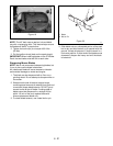
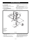
15.Install the motor thrust bearing (with the thicker
race towards the pistons) by compressing the
piston springs and sliding the bearing assembly in
to place.
NOTE:
The tool being showed is an example of what
you will need to compress the pistons and allow the
bearing to be installed.
Apply the sealant to the lower and rear housing.
NOTE:
Sealant must be of good quality, oil and heat
resistant.
16.Position the lower and rear covers onto housing
case onto the upper housing and secure with
assembly bolts. Torque the bolts from
135 to 165 in-lbs (15.2-18.6 Nm). The group of
bolts around the bottom and rear covers of the
housing have the same sequence number
because they are installed simultaneously at our
factory, the order in which you torque them should
not be important.
After torquing all bolts, wipe off any excess sealant
from the seam of the housing.
Reposition the transaxle assembly and check the
bypass actuator and axle shaft for freedom of
movement. The axle should not lock up but may be
tight, while the bypass actuator must rotate freely.
Torque the nut on the brake bolt from 120 to 185 in-lbs
(13.5-20.9 Nm)
17.Install a new lip seal on the displacement control
shaft & bypass actuator shaft.
18.Install the control arm and friction pack.
19.Install the bypass actuator arm and retaining ring.
Use care to avoid over extending the retaining ring.
Prior to adding oil to the IHT it is recommended that
you test for leaks. This may be performed with a small
hand pump or by using compressed air and a regulator.
Do not allow more than 10 PSI to be applied or seal
damage may occur. To locate a leak, apply a soap
mixture around the housing seam and at all lip seals.
7.5 OIL FILL & START-UP PROCEDURES
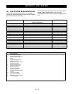
Fill the IHT with a 20W-50 engine oil. The correct
volume for fill should be 2 1/2 quarts (80 ounces).
It is recommended that the unit be purged prior to
installing into the tractor frame. The following is the
suggested purging procedures for repaired transaxle.
1. Spin the input shaft in a clockwise direction at
1000-1500 RPM This may be performed in a drill
press (or equivalent).
2. Engage (actuate) the bypass.
3. Stroke the control lever forward for five seconds
and then reverse for five seconds. Do this three
times in each direction.
4. Return the control lever to neutral.
5. Disengage the bypass.
6. Stroke the control lever forward for five seconds
and then reverse for five seconds. Do this three
times in each direction.
NOTE:
It may be necessary to repeat these steps in
the vehicle to fully purge the IHT.
CAUTION:
Most parts have critical high
tolerance surfaces. Care must be exercised to
prevent damage to these surfaces during
assembly. Protect exposed surfaces, opening
and ports from damage or foreign material.