


7 - 28
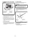
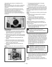
Check the oil level after fully purging the unit of air. It
should be between 1.25" and 1.62" (3.175-4.11 cm)
from the top of the housing.
After installing the IHT, make sure all linkages and
actuators and functioning properly.
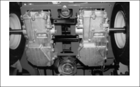
7.6 HYDRO-GEAR TRANSMISSION
REMOVAL
1. Place the unit on a flat surface and remove the
negative lead from the battery and the spark plug
lead from the spark plug.
2. Remove key and spark plug wire.
3. Raise and block the unit frame on jack stands
behind of the transaxle in the frame.
4. Remove the rear wheels by removing the lug nuts
holding the wheels to the axle hub.
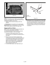
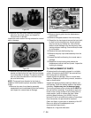
5. Release the transmission belt tension spring and
remove the transmission belt from the input sheave
on top of the transaxles.
6. Release the parking brake control rod on the top of
the units frame by pulling the hair pin and releasing
the tension spring.
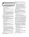
7. Tighten the shifting cam friction pack lock nut to
hold the transaxle neutral position.
8. Remove the cap screw, flat washer and locknut on
the shift rod and remove the shift rod ball joint from
the transaxle cam arm.
9. Do not remove or loosen the hardware on the
transaxle sub-frame at this point.
10.Support the transaxles subframe with a floor jack
from the rear of the tractor.
11.Remove the rear anchor strap from the transaxle
subframe and the rear of the unit.
12.Remove the two right and left front anchor bolts
holding the transaxle subframe to the tractor frame
and remove the two rear anchor bolts from the left
and right side holding the transaxle subframe to
the units frame and lower jack.
13.With the transaxle assembly removed from the
units frame, place the axle assembly on a flat work
surface.
7.7 HYDRO-GEAR TRANSMISSION
INSTALLATION
Before installing the transaxle assembly into the tractor
frame with the axle subassembly installed, the
following items will need to be done.
1. Make sure the brake rod has two flat washers and
a heavy coil spring installed on it before inserting
the transaxle into the tractor frame.
Do not tighten any hardware until all the support
hardware is installed.
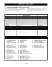
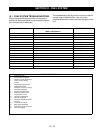
2. When all the hardware is in place, tighten to the
appropriate torque according to the hardware
torque chart.
3. Install the two flat washers, compression spring
and hair pin on the rear of the brake rod which
return/release the brake arm.
4. Install the cap screw, flat washer and lock nut on
the shift rod ball joint securing it to the transaxle
shift cam.
5. Install the transmission drive belt on the transaxle
input sheave and check the belt routing on the idler
arm and engine pulley and install idler arm tension
spring.
6. Install the dump valve rod and attach the ball knob.
7. Install the rear wheel with the lug nuts removed
earlier.
Transaxle Neutral Adjustment
1. Make sure that the rear of the unit is suspended
before the unit is started.
2. Make sure that the interlock system is operational
before proceeding.
3. Place a weight onto the seat to activate the seat to
activate the seat switch.
4. Unbolt tie rod from transaxle flange.
5. Start engine and observe wheel motion.
6. Turn transmission cam until wheel stops turning.
Tighten cam locking nut. Stop unit and connect
linkage.
7. Adjust to proper length. Unlock cam locking nut
and start engine. Test for creep. Repeat if needed.
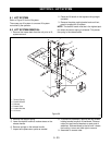
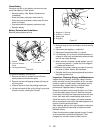
8. If neutral adjustment is needed refer to
Neutral
Adjustment
section.
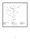
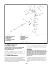
Figure 28