


11 - 39
11.6 LIGHTING CIRCUITS
Lighting circuits are simple circuits and easiest to
trouble shoot in most equipment. They consist of the
lights connected in parallel; a normally open switch, a
protective fuse and a source of power (battery or
engine alternator).
If only one light is out, check the connector, then check
the bulb for continuity (high resistance indicates a
defective or burned out bulb).
If all the lights are out, check the fuse for continuity
(high resistance indicates a defective or blown fuse).
Refer to
Fuses
. If the fuse is blown, check for a short in
the wiring and correct before replacing the fuse.
If the fuse and lamps are good, check the circuit with
an AC/DC voltmeter.
11.7 FUSES
Fuses are connected in electrical circuits to protect the
circuits from damage due to overload or short circuits.
Fuses are a "weak link" in the circuit. They contain a
metal link designed to melt when a certain current
value is exceeded thus opening or disconnecting the
wiring. Once a fuse blows or melts it must be discarded
and replaced with a new fuse of the same value.
Since the function of the fuse is to protect the circuit,
NEVER attempt to defect the protective device by
bridging or replacing with a device of a higher current
rating.
Electrical testing of these devices is simple. Since the
device either conducts current (and is therefore
functioning) or the device is open and is therefore
defective. Use an ohmmeter to check for continuity.
11.8 DIODES AND RECTIFIERS
Diodes are solid state, semiconductor devices. They
contain no moving parts and conduct current better in
one direction than the other.
Diodes allow current to flow through one circuit without
"backing up" into another. In engine alternator circuits,
a diode is used to convert current which flows back and
forth (AC) in a circuit to current which flows only in one
direction (DC). A device which converts alternating
current to a direct current is called a RECTIFIER. A
diode is one type of rectifier.
To check a diode, isolate if from the circuit by
disconnecting one end. With a multitester set on the
lowest ohms scale setting, measure the resistance in
one direction, reverse the test leads, and measure in
the other direction. Readings should be high in one
direction and low in the other. (If the readings are low in
both directions, the diode is shorted, and if the
readings are high, the diode is open.) If the readings
are the same in both directions, the diode is defective
and must be replaced.
IMPORTANT:
Diodes are marked to indicate polarity (a
band on one end, an arrow on the side, or they fit on a
holder only one way.
Rectifiers
A battery is charged through the use of an alternator
located in or on the engine. A charging circuit contains
a rectifier because alternators produce alternating
current (AC) and batteries require direct current (DC)
for charging.
The rectifier may be built into the engine or it may be
an external part. It may also contain a regulator to
prevent overcharging the battery. (Servicing of
rectifiers built into the engine should be done by an
approved engine manufacturer’s service center. Such
a service center has access to the information and
parts required to test and repair or replace engine
components, including rectifiers and regulators.)
Units that contain both a rectifier and regulator are
tested in a working circuit to make sure the regulator
portion of the device is operating.
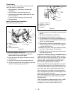
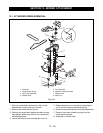
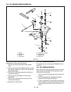
11.9 ELECTRIC CLUTCH
The electric clutch is used to turn on and off the
attachment used on the unit by use of a switch. The
clutch is also designed so that a brake is applied to the
output shaft when the clutch is disengaged (off).
The field coil is mounted to a bearing support and does
not rotate. The rotor is attached to the power output
shaft and rotates around the field assembly. The
armature is attached to the output pulley. The armature
assembly is held close to the rotor by the brake
assembly. The clutch is engaged by applying current to
the coil connection. This results in a current flowing
through the coil, magnetizing the coil pulling the
armature onto the rotor with sufficient force to hold the
two pieces together, effectively connecting the output
and the input shafts together. Pulling the armature
against the rotor pulls it away from the brake, releasing
the brake.
Engine Electrical Components
Engine servicing and repair should be referred to local
engine manufactures service centers that have the
service information and parts available to properly
service the engine. Ariens dealers should be able to
test engines and engine components to pinpoint
troubles and narrow them down to properly advise the
engine serviceman.
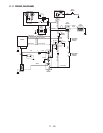
11.10 EZR ELECTRICAL
Initial check out: Make sure that all switches are in their
proper position for starting: (A) PTO off. (B) transaxle in
neutral position. (C) operator on the seat. If no battery
voltage to start the engine. Start the checklist.