


11 - 40
STEP 1
Check out the battery. Using a hydrometer on all the
battery cells to see if one or more is bad. Also use a
voltmeter to check for proper voltage. Replace the
battery if necessary and/or charge to proper level.
Refer to
Battery
.
STEP 2
Use a voltmeter to make sure you have battery voltage
to terminal (B) on the back side of the ignition switch in
the off position. If you don’t have battery voltage to
terminal (B) check the battery connection and the fuse
in the red lead.
STEP 3
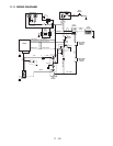
With the ignition switch in the "run" position, check to
see if the battery voltage is being transferred from
terminal (B) to terminal (A). Terminal (A) on the ignition
switch supplies battery voltage to the back of the PTO
switch on the purple lead and on to the neutral
switches on the red/violet lead to terminal S2 on the
ignition switch and to terminal 85 on solenoid #2.
Terminal (A) also supplies battery voltage to terminal
30 and 85 on solenoid #1 and on to the hour meter.
When the operator is in the seat, battery voltage will
transfer from terminal 30 to terminal 87 and on to the
front terminal of the PTO switch and on to terminal 85
on solenoid #2 in the yellow/red lead. Battery voltage is
supplied to the fuel shut off solenoid from terminal 85
on solenoid #2.
STEP 4
With ignition switch in the start position, battery voltage
is transferred from terminal S2 to S1. Terminal S1
Transfers battery voltage to the one small terminal on
the starter solenoid and goes to ground through the
base of the starter solenoid.
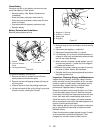
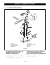
PTO clutch check out: Remove the wiring harness PTO
clutch leads from the clutch. With a multimeter check
the clutch coil for resistance to see if the coil is good.
The clutch used on models 915013, 015, 307 should
have a coil resistance of (5.87-7.87) ohms. If the coil is
bad the resistance will be higher or not at all.
The clutch used on models 915014, 016, 306 should
have a coil resistance of (1.98-3.98) ohms. If the coil is
bad the resistance will be higher or not at all.
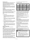
Ignition switch check out: Battery voltage check in the
"off" position, check for voltage at terminal "B". It
should not be present on terminals A, S1, S2.
With the ignition switch in the "run" position, check for
battery voltage at terminal B, A, S2. It should not be
present at terminal S1.
With the ignition switch in the "start" position, check for
battery voltage at terminals B, A, S2, S1.
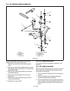
PTO switch check out: The PTO switch is a push/pull
switch with normal open and closed contacts. Power
transfer should be checked with a voltmeter. The
switch contacts should be checked with an ohm meter
with the wire harness plug removed. The light switch is
similar to the PTO switch with only one set of contacts.
Diode check out: Diodes are checked with an ohm
meter set on the diode check, and should only pass
voltage in one direction. If it passes voltage in both
directions or not at all the diode is bad and needs to be
replaced.
.
Contact resistance is 0.1-0.3 ohms when correct.
Normally open contacts manually activated. contact
resistance is 0.1-0.3 ohms when correct.
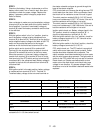
Key Switch Off Run Start
B 11.50-13.00 Volts 11.50-13.00 Volts 11.50-13.00 Volts
A 11.50-13.00 Volts 11.50-13.00 Volts
S-1 11.50-13.00 Volts
S-2 11.50-13.00 Volts 11.50-13.00 Volts
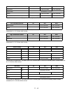
Seat Switch Off Run Start
Pink Connected to Ground through test switch
Black Connected to Ground