


7 - 26
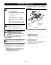
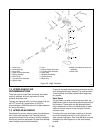
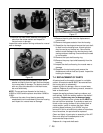
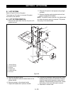
16.Remove the motor shaft, washers and bypass
plate from the center section and inspect for
unusual wear or damage.
Inspect the center section running surfaces for unusual
wear or damage.
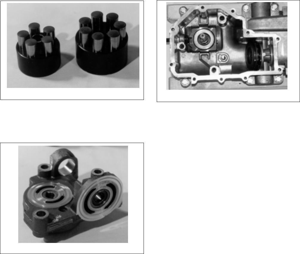
17.Remove the pump block assembly, block thrust
washer and spring from the input shaft and inspect
for unusual wear or damage. The pistons should fit
with very little side clearance in the block bores,
but must slide freely.
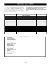
NOTE:
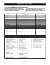
The correct bore diameter for the block is
0.6295 to 0.6303 and the pistons should be 0.6288 to
0.6291.
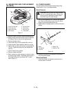
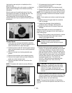
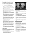
18.Remove the motor thrust bearing assembly
swashplate kit and cradle bearing from the housing
and inspect for unusual wear or damage.
19.Remove the slot guide from the displacement
control shaft.
20.Remove the bypass actuator from the housing.
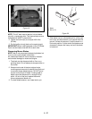
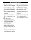
21.Reposition the housing and remove the input shaft
lip seal from the housing bore. A hook type tool
may be used to pry the seal out. Care must be
taken to avoid damage to the housing bore, shaft
sealing surface or bearing. Once removed, the seal
is not reusable.
22.Remove the input shaft bearing ring.
23.Remove the pump input shaft assembly from the
housing.
24.Inspect the shaft and bearing for unusual wear or
damage.
25.Reposition the top housing and remove the
displacement control shaft and lip seal. Inspect the
housing for damage.
7.4 REPLACEMENT OF PARTS
All parts should be thoroughly cleaned in a suitable
solvent. All sealant material MUST be removed from
the housing prior to reassembly.
Inspect all parts for damage, nicks or unusual wear
patterns. Replace all parts having unusual, excessive
wear or discoloration.
Inspect the sealing surfaces, bearing surfaces, and
shaft splines. Polish the sealing areas on the shafts if
necessary.
Replace any worn or damaged parts
.
The running surfaces of the cylinder blocks
MUST
be
flat and free from scratches. If scratches or wear are
found on the running surface of the cylinder block or
center section, polish or replace the parts, When
polishing these surfaces, up to 0.0004" may be
removed. If this is not sufficient to obtain a flat surface
free of scratches, the part should be replaced.
Clean and lightly oil parts prior to assembly of the IHT.
Be sure to torque all threaded parts to the
recommended torque levels.
Replace all o-rings and shaft seals.
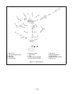
Figure 25
Figure 26
Figure 27