


7 - 25
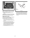
Lubricate the new seal prior to installation with a
petroleum jelly.
Wrap the shaft spline with a thin plastic or cellophane
tape to prevent damage to the new seal lip during
installation.
Slide the seal over the shaft and press it into the
housing bore. Be careful not damage the seal. The
seal should seat against the retaining ring.
The displacement control shaft seal and bypass
actuator shaft seal may be replaced following similar
procedures.
Internal Repair
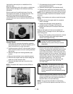
1. Drain the oil by removing the breather assembly
and positioning the IHT so that the breather port is
down to allow the oil to drain thoroughly.
2. Position and secure the IHT with the upper housing
down to allow access to the ten housing assembly
cap screws.
3. Remove the eight rear housing assembly cap
screws.
4. Remove the ten bottom cover assembly screws.
5. Remove the torques head cap screw holding the
brake arm to the transaxle case.
6. Remove the bottom and rear covers from the
transaxle.
NOTE:
The sealant will make the covers difficult to
remove.
7. All components should remain in the upper
housing (positioned down).
8. Remove the brake gear from the brake shaft.
9. Remove the oil seals from the brakes shaft. Push
out the brake shaft to remove the support bearing.
NOTE:
Prior to reassembly the lower and rear covers
must be thoroughly cleaned and old sealant must be
removed.
NOTE:
The lip seals must not be re-used during reas-
sembly.
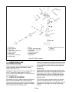
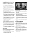
10.Inspect the final drive gear teeth for excessive
wear or damage.
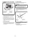
11.Inspect the brake gear internal splines for
excessive wear or damage. See Figure 24.
12.Inspect the brake cam for excessive wear and
damage.
Replace brake gear and cam as a complete kit if
excessive wear or damage is found, and inspect all
other mating parts.
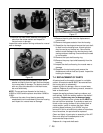
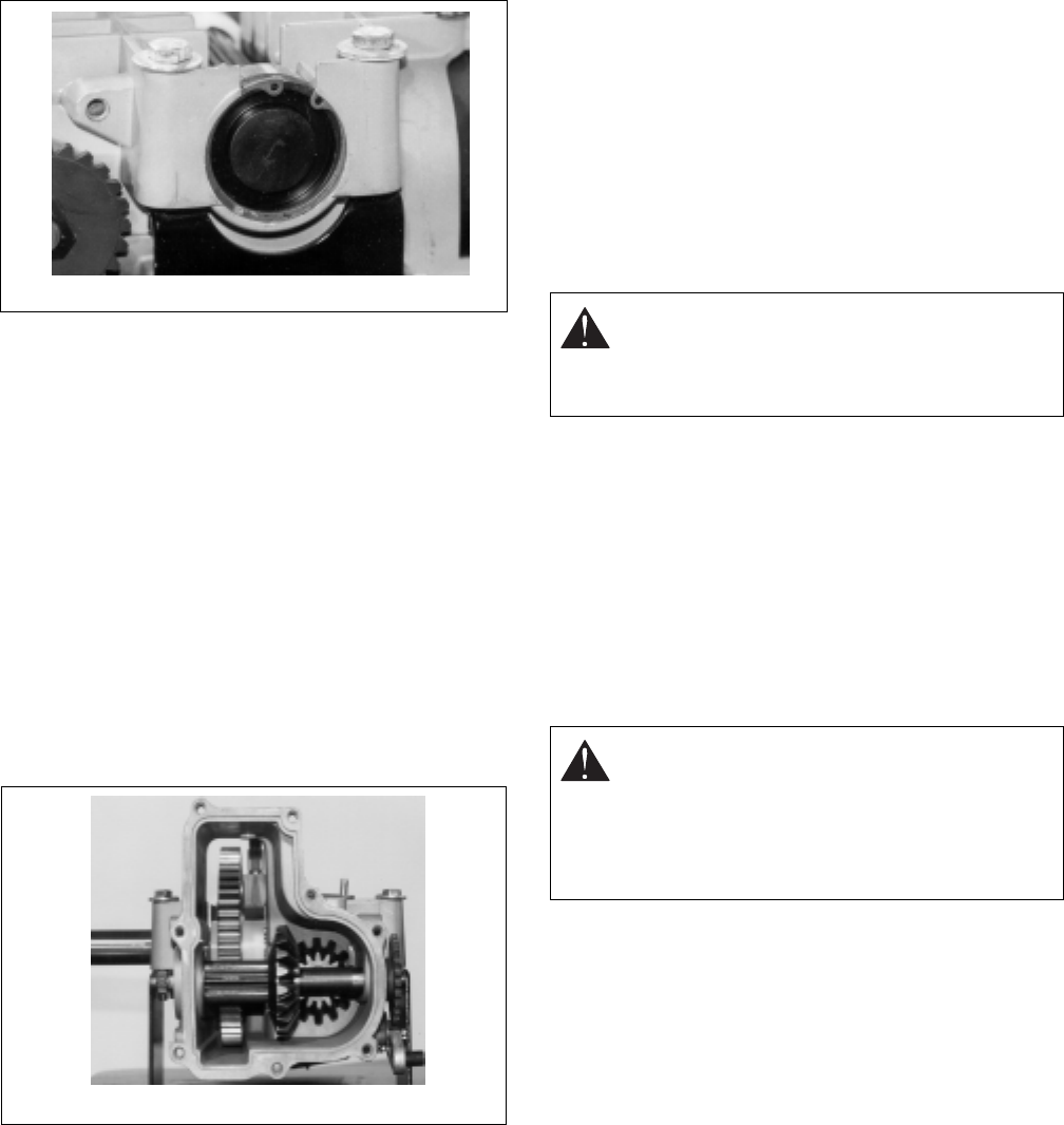
13.Using a 9/16" socket (or box end) wrench, remove
the three assembly bolts retaining the center
section in the upper housing.
14.Remove the center section assembly from the
housing. The pump block assembly should remain
in the upper housing on the input shaft, but may
stick to the center section. Check the check valve
plate bolt torque, but do not remove. Two styles of
check plates have been used, one has three bolts
while the other has four.The one with four bolts
should be torqued from 170 to 240 in-lbs.
(19.2-27.1 Nm) while the one with three bolts
should be torqued from 135 to 185 in-lbs
(15.2-20.9 Nm)
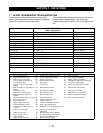
15.Remove the motor block assembly from the motor
shaft and inspect for unusual wear or damage. The
pistons should fit with very little side clearance in
the block bores, but must side freely.
NOTE:
The correct bore diameter for the block is
0.6776 to 0.6784 and the pistons should be 0.6767 to
0.6770.
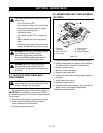
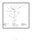
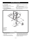
Figure 23
Figure 24
CAUTION:
The pump and motor piston
springs may push the center section
assembly out of position while you remove
these bolts.
CAUTION:
The aligning pins, motor shaft,
bypass plate, pump block and motor block
assemblies are NOT retained to the center
section or the upper housing and may
become separated from the assembly during
removal.