


4 - 13
4.10 NEUTRAL ADJUSTMENT (SPEED
CONTROL)
1. Stop the engine. Remove the ignition key. Push the
PTO knob into the "OFF" position.
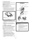
2. Place jack(s) under rear transaxles only. If jack(s)
are not available, place support blocks under both
transaxles at the rear of the unit to raise the rear
wheels off the ground.
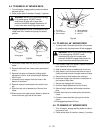
3. Remove side shrouds.
4. Place a weight on the seat to close the seat switch.
Start the engine and run it at part throttle.
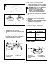
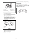
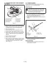
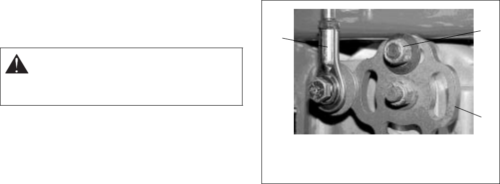
5. Remove the connecting linkage from the flange
bushing, Figure 12.
6. Rotate flange bushing until the wheel stops
rotating.
7. Lock the flange bushing in place by tightening the
lock nut.
8. Adjust the connecting rod length and reattach it to
the flange.
9. Loosen the lock nut and test by moving the
steering control levers.
10.Repeat procedure for the other side of the unit.
11.Reinstall side shrouds.
If the drive cannot be adjusted to neutral using the
above procedure, the link to the flange on the transaxle
can be adjusted.
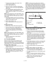
1. With the rear of the unit jacked up and supported,
remove the connecting linkage at the flange
(Figure 11).
2. Place a weight on the seat and start the engine.
Run it at part throttle.
3. Rotate the flange until the wheel stops turning and
tighten the lock nut.
4. Shut off the engine.
5. Loosen the lock nut on the connecting linkage and
adjust the rod end to match the hole in the flange.
6. Reattach the connecting linkage and tighten the
lock nut to the rod end.
7. Loosen the flange lock nut and test.
4.11 ADJUSTING THE UNIT TO TRACK
STRAIGHT
The primary reason the unit may not track straight is
incorrect or unbalanced tire air pressure.
1. First, check and adjust the tire pressure.
2. With tire pressures equal and the rear of the unit
on jack stands, check the circumference of the tire.
If one tire is larger than the other, increase
pressure in the small tire and/or decrease pressure
in the larger tire.
3. With both tires the same size, set the control
handles. The roller bearing on the speed control
arm must be in the neutral position on the neutral
detent strap.
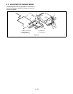
4. Adjust upper control arm linkage until the control
handles will enter the neutral switch slot and
activate the neutral switches.
5. Tighten locking nuts on the control linkage.
6. Disconnect linkage from the transmission, loosen
two cap screws in the speed control arm and
position pump weldment in the horizontal position
and tighten cap screws.
7. Start unit and by hand adjust the transmission
control cam until neutral is found.
8. Tighten a transmission locking nut.
9. Stop engine.
10.Set transmission linkage rod, then line up with hole
in control cam and install and tighten attachment
ball.
11.Loosen the transmission control locking nut.
12.Start unit and check tracking.
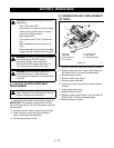
CAUTION:
PREVENT personal injury!
ALWAYS MAKE CERTAIN that jack(s) or
blocks used are stable, strong and will
support the weight of the unit.
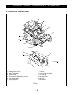
1. Connecting Linkage
2. Lock Nut
3. Flange
Figure 11
1
2
3