


© 2005 Alamo Group Inc.
Section 7 - 13
Switch Blade (JD-5105-5205-5225-5325-5425-5525, Asy. Man) 05/05
KNIFE DRIVE REPAIR / REPLACEMENT
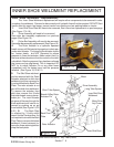
8. To reassemble the Knife Drive Assembly reverse the disassembly steps but first the cutter bar
must be made ready. If the drive stud assembly was not removed from cutterbar knife head weldment
(See Figure 22, 23 & 27) and you do not plan to loosen the clamp around the nylon nearing on knife drive
stud, you will not need to do this. IF the drive stud is removed the cutter bar head clamp will need to be
prepared. Loosen the clamp bolt to where the nylon bearing (bushing) can be installed into the clamp,
reinstall the clamp bolt into clamp BUT DO NOT tighten clamp bolt. Insert the drive stud bearing into the
nylon bearing of clamp, still DO NOT tighten the clamp bolt.
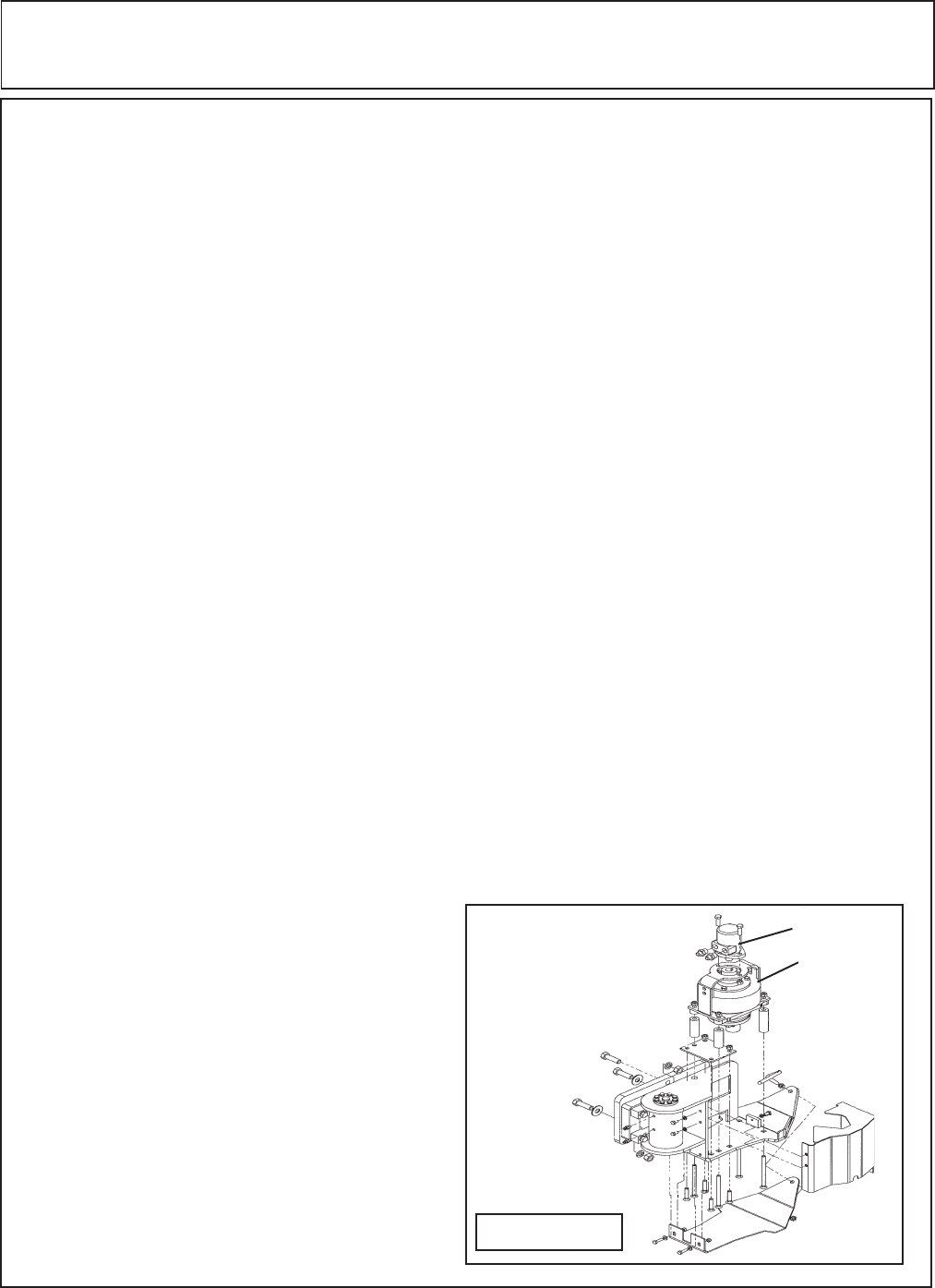
9. Install the support bracket to the lower side OD the knife drive assembly, these e are two 8 mm
bolts that screw into the knife drive assembly bottom side. Torque the 8 mm bolts to 20 ft. lbs.
10. Install the Tube spacers over the carriage bolts, remember the long ones go in the front and the
short ones go in the rear. Set the drive assembly down over the four bolts where it is setting on the four
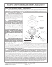
tube spacers. Install the motor adapter down over the same four bolts (See Figure 28), The Drive
assembly can be tightened down now, these are 1/2" grade 8 plow bolts and should be torqued to 100
to 110 ft. lbs.
11. From the bottom of the drive assembly turn the drive assembly, (there are holes in the outer
diameter of the flywheel that can be used to turn it by inserting a bar into the hole). Align the drive assembly
support bracket with the two bolt holes for the drive stud bearing, KEEP YOUR HAND away from the
cutting blades they are sharp. After the two 10 mm bolts are installed into the drive stud bearing torque
them to 35 ft. lbs. The drive assembly can be checked prior to bolting on the motor. Use a punch or rod
that can be inserted into the hole on the OD of the flywheel (KEEP YOUR HANDS OUT OF THE KNIVES).
This will check to make certain the cutter bar is not binding and also check to make certain the drive stud
bearing is rotating freely.
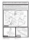
12. With the drive assembly bolted down to the skid shoe weldment and the knife drive stud bolted
to the support bracket at the bottom of the knife drive assembly. The Clamp Bolt on the knife head
weldment will need to be tighten down, CAUTION MUST BE USED when tightening the clamp bolt to
prevent the knife drive stud beading from being damaged. Before tighten you should be able to slide the
knife head weldment with the nylon bearing in it to slide the bearing and knife head weldment up and down
slightly on the knife drive stud bearing. Slowly tighten the clamp bolt checking this up and down
movement. When you have tighten the clamp bolt and all the up and down movement between the knife
head weldment (Nylon Bearing) is removed the clamp bolt will be tight enough. Do not over tight clamp
bolt as damage to the knife drive stud bearing can be damaged. The Knife head weldment clamp has
to be in the right position up and down on the knife drive stud bearing so the cutter bar in center for height
to match the cutter bar.
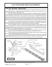
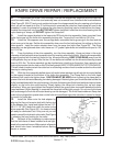
Figure 28
13. Install the Motor onto the hub adapter by
aligning the Key on the motor shaft with the key slot
in the adapter hub. Install and tighten the two 1/2"-
NC X 1-1/4" GR 5 bolts that retain the motor to the
drive assembly (See Figure 28 ). the hoses should
all ready be connected, but if they are not you will
need to consult the hydraulic schematic (See Figure
1) showing the hose routing for the motor.
14. Recheck all the installation to make certain
that the bolts have all been installed and are tight-
ened to the required torque. Make certain all guards
and shield have been reinstalled before starting
tractor or mower.
Motor
Knife Drive
Asy